
Condenser Mike Pre-Amplifier Circuit
COND MIC,
need often arises for a sensitive sound pick-up device, whether it is to be used as a simple microphone or a more exotic device as a sound operated alarm, a bugging device or a sound operated flash (for stop action photography) the list is quite unending. Below mic preamp circuit use two npn transistors.
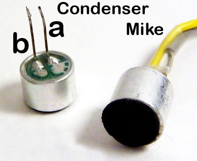
The circuit given employs a condenser microphone as the transducer. Since output of the condenser microphone is quite low, it usually has an FET amplifier built into the case.

| PARTS LIST | |
| R1 | 1.2k |
| R2 | 2.7k |
| R3 | 33k |
| R4 | 6.8k |
| R5 | 3.3k |
| R6 | 100 |
| R7 | 560k |
| R8 | 4.7k |
| R9 | 1k |
| VR1 | 10k |
| C1 | 47µF 10V |
| C2 | 0.1µF |
| C3 | 0.1µF |
| C4 | 220µF 10V |
| C5 | 10µF 10V |
| Q1 | BC149C |
| Q2 | BC147B |
| MIC | Condenser Mike |
This amp is powered by the R1, R2 resistor network.
The output of condenser microphone is fed to a two stage amplifier. Transistor T1 (BC149C) utilising current series feedback forms the first stage. The second stage comprising transistor T2 (BC147B) is connected in the voltage shunt feedback configuration. These two stage provide sufficient gain to pick up even the slightest whisper.
The circuit requires a 4.2 volt supply.This may be obtained, as in the prototype, with a 1kΩ (R9) resistor as shown in the diagram. The value of this resistor may be altered. to suit a supply voltage other than 6 volts.
Output of the microphone amplifier can be made variable by connecting a 10kΩ potentiometer / Preset as shown.
This mic preamp circuit gain can be increased by reducing the value of R6 to 47Ω or 22Ω, depending on the input sensitivity of the main amplifier system. Increase in gain was also observed by using 3V supply and eliminating R9 altogether. The microphone should be housed in a small round enclosure.
Please send your ideas, which are very important for our success…
This circuit works great!, how can i reduce some of the background noise leaking through the circuit?
Hi Taylor shift the volume control between mic and Q1. It will solve your problem
Really awesome article! Honest..
This circuit works great!, how can i reduce some of the background noise leaking through the circuit?
Incredibly great read. Truely.
Hi Taylor shift the volume control between mic and Q1. It will solve your problem
amazing things thanx
Bookmarking now thanks, found you through Bing.
You seem very knowledgeable in your field.
It is very usefull
thanks
Hi this really helped me a lot, however would it be possible to incorporate a on/off power switch for the battery or voltage source?
Also how would I hook this preamp circuit to an amplifier circuit?
Also would it be possible for you to send me some pics of the finished circuit?
hi sir,
can i know what is this circuit exactly?i think that when i speak from mic the sound will be heard by the output[speaker]am i right please tell me because i am a beginner.
thank-u
this circuit is grate
Hello newbie here… I would like to ask if theres any substitute for the transistors because they are not available here. Thanks 🙂