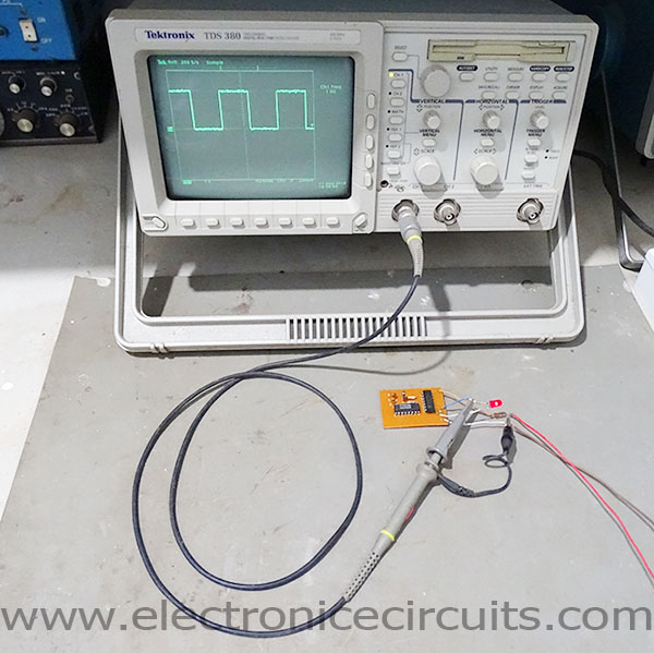
This is One Hertz (1Hz) clock generator circuit using 32.768Khz crystal, CD4060 and CD4013 ICs. Our circuit base on crystal oscillator. So we can get very accurate and stable output. That can use for clock, timers and many projects.
| PARTS LIST | |
| R1 | 10MΩ |
| R2 | 330KΩ |
| C1 | 33pF Ceramic |
| C2 | 33pF Ceramic |
| C3 | 0.1µF Ceramic |
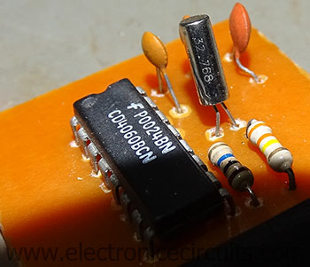
| IC1 | CD4060 |
| IC2 | CD4013 |
| XTAL | 32.768KHz |
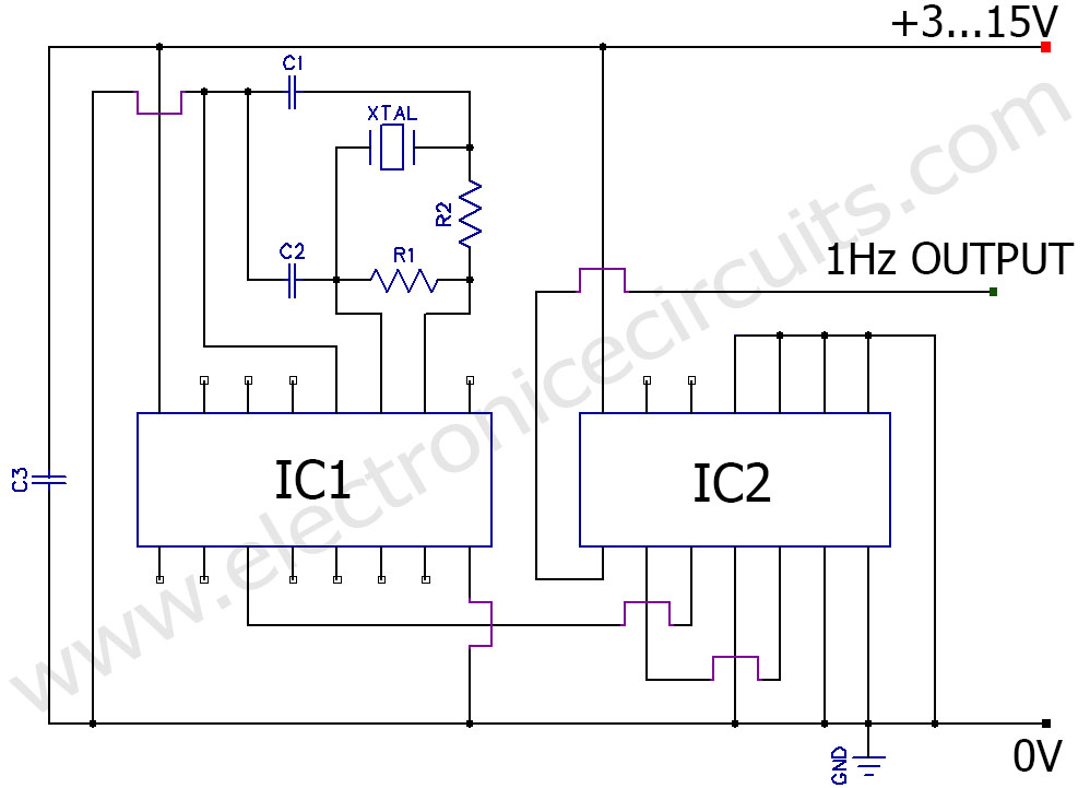
XTAL is 32.768KHz crystal. That is a very commonly use in digital clock.
R1 use as bias resistor and R2 use as a current limiting resistor. Also C1 and C2 are load capacitors.
Let’s check how we get 1Hz output.
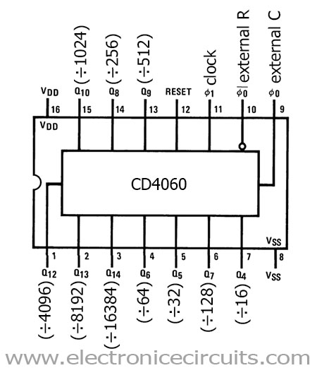
We need to divide our crystal frequency by 215 to get 1Hz. Because CD4060 act as an oscillator and frequency divider. here it is arranged to divide by 16384 which gives 2Hz when you using 32.768KHz crystal.
32.768KHz/214=2Hz
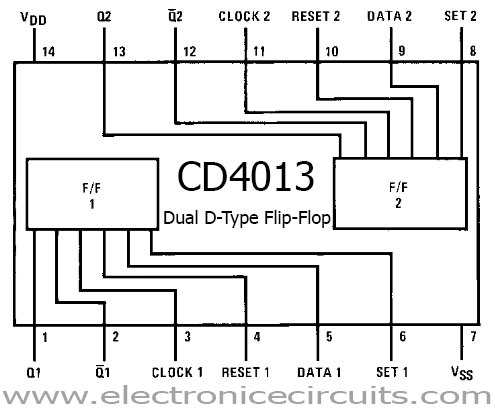
Then we use CD4013 dual D-Type Flip-Flop as a frequency divider. But circuit use only one D-type flip-flop. It divides our frequency by 2. Now we can get 1Hz output. Other D-type flip flop is not used and it connects to the ground.
This circuit accuracy slightly depends on crystal quality and ambient temperature. If you have a high accuracy frequency meter you can slightly adjust frequency by changing C2 capacitor valve and you can use 50pF variable capacitor for C2 to do that. You can connect a frequency counter to CD4060 number 9 pin (External C) and adjust C2 to read exactly 32.786KHz. This is not necessary for our normal projects.
Precision 1Hz clock generator circuit PCB design
| Precision 1Hz clock generator circuit PCB Layout | 1Hz Oscillator Circuit PCB Copper Tracks with Drilling Holes | CD4060 1 hertz crystal oscillator pcb Component Side |
| 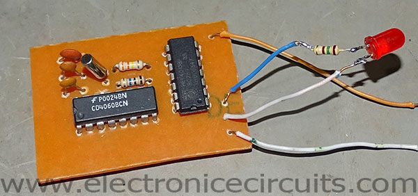 | 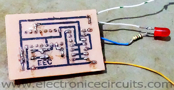 | 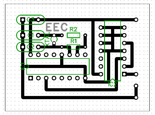 |
Please send your ideas, which are very important for our success…
Hi, can u make it?
Device Specs
Frequency Range: 0.01 – 999Hz programmable
Wave Form: Square pulses
Duty Cycle: 50%
Current Intensity: 20μA to 400μA
Constant current generator
Output Polarity: Programmable alternating, positive or negative
Output Channels: Two fully independent channels
Memory: Professional- holds up to 100 programmable protocols