
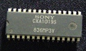
CXA1019 FM RADIO Circuit
CXA1019 is a one-chip FM/AM radio IC designed for radio-cassette tape recorders and headphone tape recorders, and CXA1019S has the following functions.
CXA1019 Features
- Small number of peripheral components.
- Low current consumption (Vcc=3V)
For FM: I0=5.3 mA (Typ.) - Large output of AF amplifier.
Vcc=6V, EIAJ output=500mW (Typ.) when load impedance 8Ω.
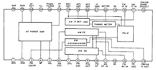
Functions FM section
- RF amplifier, Mixer and OSC (incorporating AFC variable capacitor).
- IF amplifier
- Quadrature detection
- Tuning LED driver
CXA1019 Structure
- Bipolar silicon monolithic IC

| PARTS LIST | |
| R1 | 100KΩ |
| R2 | 2.2KΩ |
| VR1 | 50KΩ Volume Control |
| D1 | Red Colour LED (Tuning Indicator) |
| C1 | 15pF |
| C2 | 4.7µF |
| C3 | 4pF |
| C4 | 0.02µF |
| C5 | 22pF |
| C6 | 20pF |
| C7 | 100pF |
| C8 | 22pF |
| C9 | 0.01µF |
| C10 | 220µF |
| C11 | 4.7µF |
| C12 | 10µF |
| C13 | 1µF |
| C14 | 0.27µF |
| C15 | 1000pF |
| C16 | 100µF |
| C17 | 0.1µF |
| C18 | 100µF |
| FM T/C | FM Tuning Capacitor (15-30pF) |
| IF | Orange Colour FM IF Transformer |
| CF1 | 10.7 MHz FM Ceramic Filter |
| L1 | 2¾ (2.75) Turns of 22 swg enamelled copper wire close-wound on a 5mm diameter. |
| L2 | 3¾ (3.75) Turns of 22 swg enamelled copper wire close-wound on a 5mm diameter. |
| Aerial | Telescopic Aerial OR 100cm Circuit Wire |
| SP | 2W 8Ω Speaker |
| IC | CXA1019 s |
TUNING CAPACITOR
 |  with AM") |
| In this circuit diagram we have mention about FM tuning side only.When we assemble the Tuning Capacitor, we must be careful to select correct side of tuning capacitor.Normally in the FM side of the tuner middle pin and other pin capacitance will be nearly 15pF to 40pF. Middle pins: B and F, FM side:A,B, C in this photo. | |
CXA1019 TUNING COILS
 |  |
| 2¾ (2.75) Turns of 22 swg enamelled copper wire close-wound on a 5mm diameter. | 3¾ (3.75) Turns of 22 swg enamelled copper wire close-wound on a 5mm diameter. |
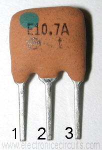
IF Transformer
 |  |  |
| 1 and 3 pins used to this circuit. | ||
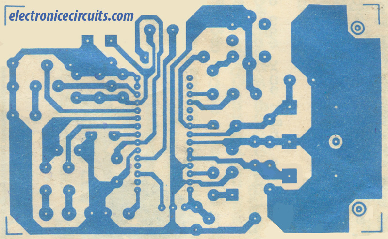
CXA1019 PCB
 |
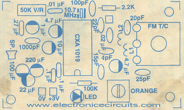 |
| width=7.95 cm Height=4.90 cm |
Please send your ideas, those are very important for our success…
If somebody wants sony doc pl ref following site
http://pdf1.alldatasheet.com/datasheet-pdf/view/115246/SONY/CXA1019AM.html
it is ok just simple to adjust the design
on the if it is copied
The Diagram So Very Nice !
thanks ! ! !
I’m very interested with this design can I order the materials from your through western union money transfer and get them so that I may real experience it?
please if ok let me know.
is there any specification for IF transformer ?? shopkeeper doesn’t understand ORANGE color….
thanx..
If you can’t find out IF Transformer, replace 10.7 two pin ceramic filter. Audio output will increase and tuning part become easy. Good Luck !
please if i need to suimulate this this circuit on orcad how could i find CXA1019s or FM Tuning Capacitor
Nice presentation!
Thanks.
CXA1619BS is a powerful IC.
please post am AM/MW reciever (only AM) diagram with bar antenna.
nice diagram…
can you provide also the am/fm radio circuit??
can i ask what is a simulator program that you used in trying this circuit… i try using the tinycad but i don’t
see some items listed…
can i use red if transformer instead?what are other alternatives if orange if transformer is not available?
please i need the data sheet of cxa1019s whigh in the wirless alarm car circit which is
very good performance
Super presentation
Hello, can any one tell me plz, how to identify diodes?
hai i ask one doubt if cxa1619 is similar to cxa1019 please reply to me
thanks and regards,
N.saravanan
good
ic cax1619 pin 14 fm Receivercircuit diagram
The discriminator transformer is of the “quadrature” type. In this application it is the same as the Xicon 42IF124 (approximately 4.5uH in parallel with a 51PF capacitor. The ceramic discriminator (LT10.7) will give greater volume and reduce adjustments but at slightly higher distortion.