
FM Booster, Active FM Antenna Amplifier Circuit
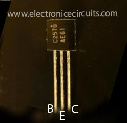
This FM booster circuit that can be used to listen to programs from distant FM stations clearly. The circuit comprises a common-emitter tuned RF preamplifier wired around VHF/UHF transistor 2SC2570. (Only C2570 is annotated on the transistor body.)

| PARTS LIST | |
| R1 | 27kΩ |
| R2 | 270Ω |
| R3 | 1kΩ |
| C1 | 5.6pF |
| C2 | 5.6pF |
| C3 | 1n |
| C4 | 10pF |
| C5 | 10pF |
| C6 | 0.1µF |
| VC1 | 22pF Trimmer capacitor |
| VC2 | 22pF Trimmer capacitor |
| L1 | 4T, 20 SWG 5mm DIA, AIR CORE TAPED AT 1T FROM BOTTOM END |
| L2 | 3T, 20SWG 5mm DIA, AIR CORE |
| T1 | 2SC2570 |
Assemble the circuit on a good-quality PCB (preferably, glass-epoxy).
Adjust input/ output trimmers (VC1/VC2) for maximum gain.
Input coil L1 consists of four turns of 20SWG enamelled copper wire (slightly space wound) over 5mm diameter former. It is tapped at the first turn from ground lead side. Coil L2 is similar to L1, but has only three turns.
Please send your ideas, those are very important for our success…
pcb
Hi dolfin use straight track general purpose PCB or dot matrix pcb. even a plain laminate with holes and connecting inserted component through bare hook up wire is sufficient being vhf. a very nice circuit use only C2570 for best performance.
good and simples….
bravooo
Hi, great work. very simple . I just wanted to ask can i use this for ham radio?
Thanks