
In Circuit Transistor Tester Schematic
Here is a circuit that can indicate the condition of a transistor by using two LEDs. A good NPN transistor conducts during the positive half cycle (pulses are generated by 556 dual timer) and D5 is off while D6 flashes. With a good PNP transistor D6 is off and D5 Flashes.

| PARTS LIST | |
| R1 | 470kΩ |
| R2 | 470Ω |
| R3 | 470Ω |
| C1 | 0.47µF (Electrolytic) |
| D1 | 1N4148 |
| D2 | 1N4148 |
| D3 | 1N4148 |
| D4 | 1N4148 |
| D5 | RED LED |
| D6 | GREEN LED |
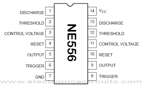
| IC1 | NE556 |
Both LEDs flash if the transistor is open and will be off if it is shorted.
The tester checks the transistor even if in-circuit resistance across the transistor is as low as 50 ohms; below this the glow becomes dim. Diodes in the ensure that only low saturation voltage of a good transistor turns the LED off.
| Condition of LEDs | |||
| S.No. | Transistor | LED D5 | LED D6 |
| 1 | Good NPN | Off | Flashing |
| 2 | Good PNP | Flashing | Off |
| 3 | Open Circuit NPN of PNP | Flashing | Flashing |
| 4 | Short Circuit NPN or PNP | Off | Off |
Please send your ideas, which are very important for our success…
will this In Circuit Transistor Tester work I have built it but no go…
found your site on del.icio.us today and really liked it.. i bookmarked it and will be back to check it out some more later
Have very carefully built this too but no joy at all.
Suspect I need to ground unused inputs or something but am not sure, also suspect that voltage rating on electrolytic may be important as it powered up lighting both LEDs dimly after some minutes with a 0.47uF 50V cap which was the lowest value I had on hand.
Anyone actually had it going and happy with it? If so what did you do with unused inputs exactly.
Just want to build a basic transistor checker that works reliably
This is not working at all; what is the error? Schematic or parts?
Hi every one:
This circuit works, the only problem was that
pin 9 has to be connected to pin 6 and 2.
Hi Abe,
On the schematic, it has clearly shown that pin 9 should not link to pins 2 & 6.
Have you assembled one?
Thank and best regards,
I have assembled one and it works perfectly. Just connect pin9 to pin 6 and 2.
This circuit will not identify Collector and Emitter. If you reverse them, the circuit will still display OK.
this circuit work fine Ijust conect pin 9 topin 2and 6 and change c1 to 470uf 16v for bether flashes.
this circuit work good, but I replace ci from .47uf to 470uf 16 v and I get better rate on the led flashing……..Thanks
I did how you say connect pin 9 to pin 2 and 6 and capacitor to 470 uf 16v and when I turn on always green led is on even if I didn’t connect to tranzistor
good job, but do you have the PCB Design of this Tester ???
Thank you …
solder a wire from pin 9 to 6& 2 pins replace capacitor 470 uf to 1uf built and tested