
Momentary push button soft latching toggle on off switch circuit
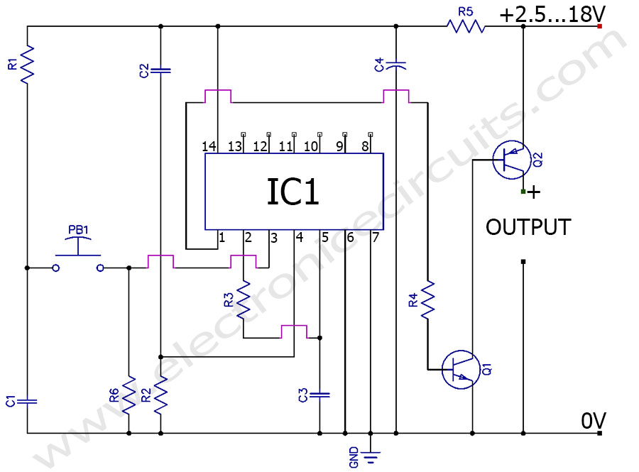
This is a momentary push button switch to latching circuit for toggling electronic devices ON and OFF. When you push once this circuit set to ON and push again circuit set to OFF.
Another advantage of that circuit is a some loads need to be switched on from one location and switched off from another. Any number of momentary push buttons can be connected in parallel.
The circuit is off when we connect power to the circuit. That one is very good feature because many circuits are on when we connect to power.
There is no current flow when circuit is off. Actually circuit flow ≈ 10µA ≈ 0A. So this is very good for battery powered circuits.
Our push button switch also control positive side of the power supply using Sziklai Pair Configuration. So you can used this circuit for meal chassis devices. The Sziklai pair (compound pair) is a configuration of two bipolar (One NPN and One PNP) transistors, similar to a Darlington pair.
| PARTS LIST | |
| R1 | 1MΩ |
| R2 | 10KΩ |
| R3 | 100KΩ |
| R4 | 47KΩ (SEE NOTE) |
| R5 | 22Ω |
| R6 | 1KΩ |
| C1 | 0.1µF (104) |
| C2 | 0.1µF (104) |
| C3 | 0.1µF (104) |
| C4 | 1µF 50V |
| Q1 | 2SD400 |
| Q2 | 2SB507 |
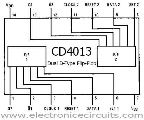
| IC1 | CD4013 |
R4 must vary with supply voltage. Otherwise Q1 heat up or not proper bias Q2.
R4 ≈ (9×Supply Voltage)KΩ
Our push button switch circuit made using single flip flop. The output changes state every time flip-flop gets a positive pulse on the input.
The CD4013 IC contains two separate D-type flip flops and used one flip flop for our circuit.
All mechanical switches has bounce when switching, the contacts make and break several times before switch on or off. This effect reduces by adding C1, R1 and R6.
Fast switching on and off won’t work because the de-bounce circuit puts in a very small delay while C1 recharges through R1. It is not a problem in real life usage.
The circuit is off when it power up controlling by C2 and R2.
 | |  |  |
Please send your ideas, which are very important for our success…
all time glade us
What is the maximum safe load current through Q2 using the 2sb507 (heatsinked or bare)?
Thanks it wocks
Really useful circuit, thanks. Works great.
One question – what is C4 for? what does it do?
Thank you
Hi,
Great little circuit – I have been looking for this for some time.
I will be using this switch circuit to switch a Lithium Ion 3.7V/4.2V battery pack.
Due to space constraints I will have to use SMD devices.
Do you know the equivalent surface mount devices for Q1 and Q2?
Can C4 be a ceramic capacitor?
Many thanks.
What happens when the switch is closed and held closed indefinitely? Will the output remain in its transferred state?
Hi there,
Can I use other transistores?
NC