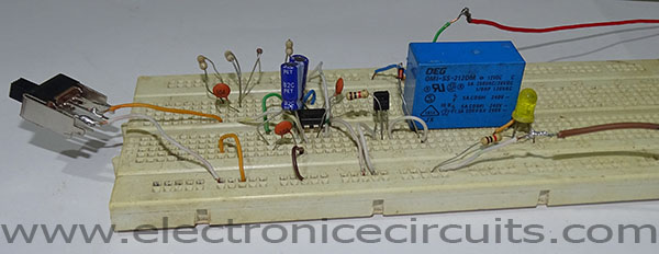
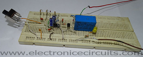
This is a toggle switch to momentary (latch to push button) switch converter. Most of the time we need momentary to toggle switch. But sometime we need to convert some latch signal to momentary signal. Our circuit convert toggle switch constant ON action into a momentary ON action. This circuit base on 555 timer IC and it uses monostable mode.
| Parts List | |
| C1 | 0.1µF Ceramic |
| C2 | 10µF 25V Electrolytic |
| C3 | 0.1µF Ceramic |
| C4 | 10µF 25V Electrolytic |
| C5 | 0.1µF Ceramic |
| R1 | 47kΩ |
| R2 | 47kΩ |
| R3 | 10kΩ |
| R4 | 1kΩ |
| D1 | 1N4148 |
| D2 | 1N4148 |
| Q1 | 2N3904 |
| RL1 | Relay (voltage same as supply voltage) |
| IC1 | 555 Timer IC |
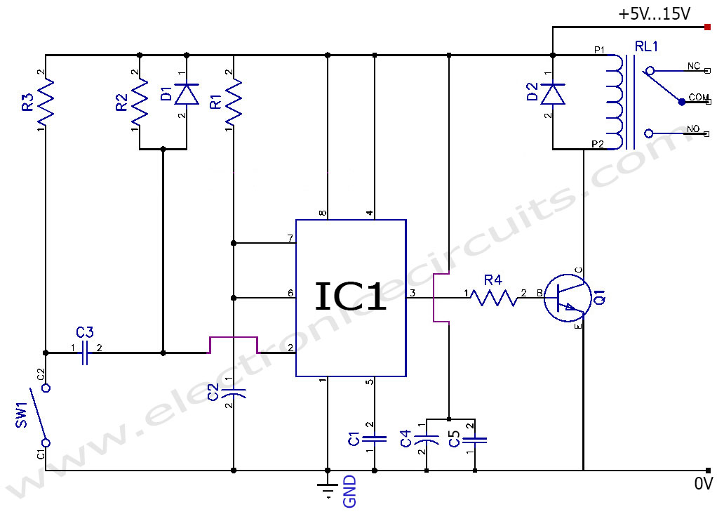
The Monostable 555 Timer circuit triggers when negative pulse applied to pin 2.This negative pulse need to go down 1/3Vcc. Once triggered, the 555 Monostable will remain pin 3 output on until the time period (T) set up by the R1 × C2 network has elapsed.
T= 1.1 ×R1 × C2
T in seconds, R in Ω and C in Farads
T=1.1 × (47× 1000) × (10/1000000)
=0.517 ≅ 0.5 seconds
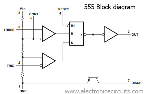
555 timer IC block diagrams and pin information
When the switch is closed C3 capacitor will charge through the SW1 and R2, Because the voltage at pin 2 move below 1/3Vcc. Then 555 triggers and start timing cycle. The output at pin 3 immediately moves up to near the supply voltage and remains at that level until the C2 timing capacitor charges to about 2/3 of the supply voltage. When the switch is open, the C3 capacitor discharges through the R2 and R3 resistors. The D1 across the R2 prevents the voltage at pin 2 from rising above the supply voltage when the capacitor discharges.
Update1: Toggle to Momentary Switch Youtube Video
 |  | |
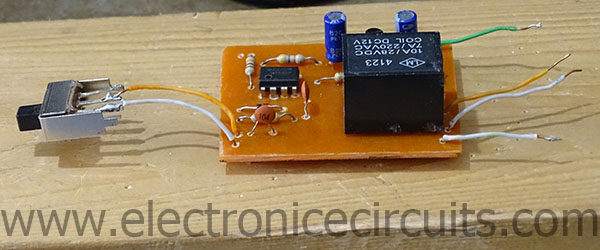
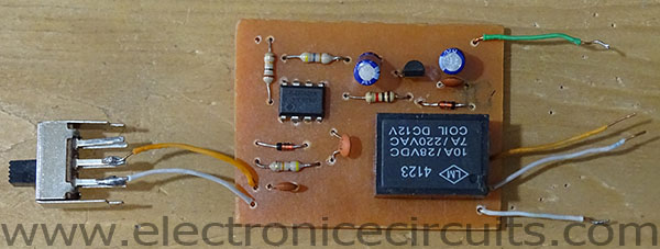
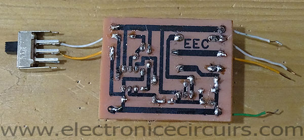
Update 2: Toggle to momentary switch PCB design
 |  |  | 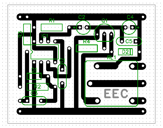 |
Please send your ideas, which are very important for our success…