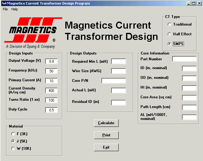
Current Transformer Design Software
This design routine assists design engineers in choosing the most appropriate core material and size for a number of different current transformer (CT) topologies. Namely, the following three CT styles are included:
* “Traditional” (often line frequency) Current Transformers – “Traditional” Current Transformers fall into a general category known as instrument transformers. Their main purpose is to produce, from the primary current, a proportional secondary current that can easily be measured or used to control various circuits. The primary winding is connected in series with the source current to be measured, while the secondary winding is normally connected to a meter, relay, or a burden resistor to develop a low level voltage that is amplified for control purposes.
* Hall Effect Current Transformers – The characteristics of a Hall Effect generator make it suitable for detector elements in magnetometers, clamp-on DC-AC ammeters, transducers, magnetic field variation meters, and wattmeters.
In the specific case of current sensors, the Hall generator/sensor is placed within air gap of a magnetic core. The core is usually a toroid, and features a soft magnetic material (such as ferrite, Molypermalloy powder, or Kool Mu®). An initial core size is chosen to support the central primary conductor, and a gap is estimated to accommodate not only the thickness of the Hall Sensor itself, but also to ensure that the correct flux field will be set up within the core material at the sensor’s peak current to be detected.
* SMPS Current Transformers – Current Transformers for SMPS designs are used to sense current levels within the control loop of the power supply. The current transformer in this scheme (usually made using a ferrite toroid) helps to track the current in the control circuit’s feedback loop. This current is then used to determine how the future behavior of the SMPS will be modified. For instance, the duty cycle (for pulse width modulated systems) might be altered for future switching cycles.
Source: MAGNETICS Applications Engineering Email: magnetics@spang.com
Please send your ideas, those are very important for our success…
DOES IT REQUIRE INTERNET CONNECTION
IT DOESN’T REQUIRE INTERNET CONNECTION.
Please tell your problem..
Very nice information.
I really liked your blog! great
Thanks for the info about the current transformers design software.Can I get to see the trial version of this software?
Can i receive trial version software
This software is easiest way to calculate the C.T. ratings.
Dear sir I am interested in different in design of oil field and gas filled cts of 132 kv rating?
i like it
Hello. Thank you. Was very nice.