Ultra Simple Digital Probe Circuit
Digital Probe circuit is an essential instrument for any electronic engineer working on digital circuits. The described here can show all the four digital states through two LEDs. It can be used for both TTL and CMOS ICs.
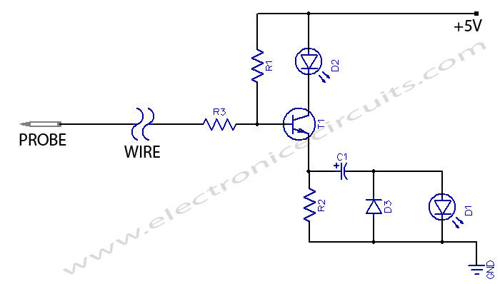
The probe has two LEDs red and green. When the probe is not attached to anything, or if it is thuched to a point which is in tri-state, the green LED will glow dimly. The green LED will stop glowing if the probe is on ‘low’ logic state. If the probe is put on a ‘high’ logic state the green LED will glow brightly. The red LED will glow when a pulse train is present. However, if a very slow pulse is present then the green LED will go on and off but the red LED may not glow.
The probe will take power supply from the device under test. As the power requirement is about 7 mA it should not pose any major problem to the power supply of the device under test.

| PARTS LIST | |
| R1 | 100 KΩ |
| R2 | 220 Ω |
| R3 | 2.2 KΩ |
| C1 | 50µF 16V |
| D1 | RED LED |
| D2 | GREEN LED |
| D3 | IN4001 |
| T1 | BC 148C |
A forward biasing resistor (R1) of high resistance is connected to the case of transistor T1. Due to this resistor a small current passes through the resistor-diode limb (R2,D2) and the green LED glows dimly.
When the probe touches a ‘high’ logic point, T1’s collector current increases and the LED starts glowing brightly. Presence of a low logic state stops flow of current through T1’s collector circuit and the LED stops glowing.
When a pulse is present emitter of T1 goes alternately ‘high’ and ‘low’. The resulting AC component of the pulse is passed through capacitor C1. this current gets rectified by D3 and red LED glows. Input impedance of the circuit is of the order of 100k.
As the circuit uses very few components, it can be constructed on a general-purpose PCB. For ease of use, LEDs should be placed near the probe. Power supply cables should be placed at the farther end from the probe.
Please send your ideas, those are very important for our success…
“The probe will take power supply from the device under test. As the power requirement is about 7 mA it should not pose any major problem to the power supply of the device under test.”
Shouldn’t it be 1mA??