Six-LED Bar Power Indicator for audio amplifier
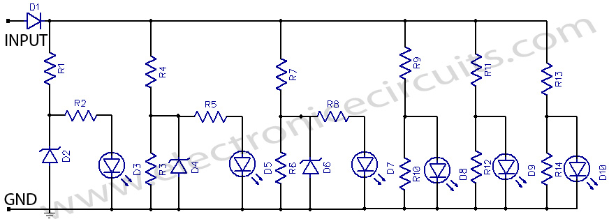
Useful to monitor audio power delivered to loudspeakers, No power supply – no setup required, This device, connected to the loudspeaker output of an audio amplifier, will indicate the instantaneous output power delivered to the loudspeaker(s) by means of six LEDs illuminating one after another by voltage values increasing little by little, providing the visual impression of a luminous bar or column, increasing and decreasing in height following the increase and decrease of the signal’s level.
The input signal is first rectified by D1 and then sent to six different voltage dividers, one for each LED. In this way, the indication provided by the LEDs illumination of this “Power Display”, will be related to the instantaneous power sunk by the whole loudspeaker cabinet. Six output power levels are displayed by the LEDs in a 2W – 80W range (no setup required). Each nominal power level indication into 8 Ohms load is reached when the respective LED illuminates at full brightness.

| PARTS LIST | |
| R1 | 220Ω 1/2W Resistor |
| R2 | 100Ω 1/4W Resistors |
| R3 | 220Ω 1/2W Resistor |
| R4 | 330Ω 1/2W Resistors |
| R5 | 100Ω 1/4W Resistors |
| R6 | 100Ω 1/4W Resistors |
| R7 | 330Ω 1/2W Resistors |
| R8 | 100Ω 1/4W Resistors |
| R9 | 560Ω 1/2W Resistors |
| R10 | 100Ω 1/4W Resistors |
| R11 | 820Ω 1/2W Resistors |
| R12 | 100Ω 1/4W Resistors |
| R13 | 1.2KΩ 1/2W Resistors |
| R14 | 100Ω 1/4W Resistors |
| D1 | 1N4004 400V 1A Diode |
| D2 | BZX79C2V7 2.7V 500mW Zener Diodes |
| D3 | Red LEDs (Any dimension and shape) (See Notes) |
| D4 | BZX79C2V7 2.7V 500mW Zener Diodes |
| D5 | Red LEDs (Any dimension and shape) (See Notes) |
| D6 | BZX79C2V7 2.7V 500mW Zener Diodes |
| D7 | Red LEDs (Any dimension and shape) (See Notes) |
| D8 | Red LEDs (Any dimension and shape) (See Notes) |
| D9 | Red LEDs (Any dimension and shape) (See Notes) |
| D10 | Red LEDs (Any dimension and shape) (See Notes) |
Notes:
- The output power indicated by each LED must be doubled when 4 Ohms loads are driven.
- The circuit can be adapted to suit less powerful amplifiers by reducing the number of LEDs and related voltage dividers.
- LEDs of any dimension can be used, but rectangular shaped devices will be more suitable to be compacted in bars or columns.
- For a stereo amplifier, two identical circuits are required.
Please send your ideas, those are very important for our success…