Skip to content
Electronic Circuits

DIY Hobby projects, diagram, schematic

Electronic Circuits

DIY Hobby projects, diagram, schematic

12W Amplifier Using 741 Op Amp

electronicecircuits, August 3, 2009August 20, 2023
12w-amplifier-circuit-using-741-op-amp


12W Amplifier Circuit Using 741 Op Amp

A 12 watt audio amplifier operating on a dual symmetrical supply of ± 12 volts. The 741 provides the required gain while the speaker drive is provided by the complementary Darlingtons T1, T2 and T3, T4.
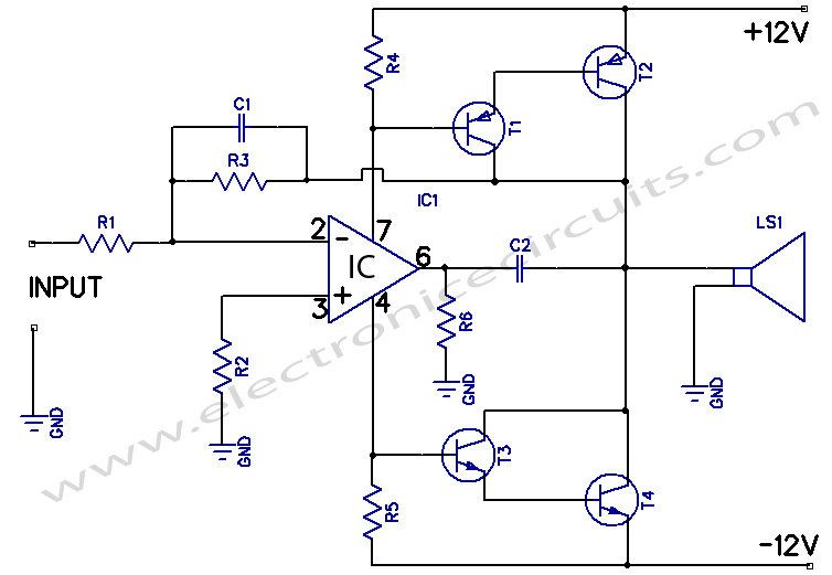
12w amplifier circuit using 741 Op amp IC

PARTS LIST
R110KΩ
R24.7KΩ
R3270KΩ
R41KΩ
R51KΩ
R647Ω 1W
C150 Pf
C20.01 µF
T1BC178
T22N6107
T3AC108
T42N5294
ICLM741
LS150W 4Ω

The input signals for the darlingtons are derived from the supply current of the 741. Since R6 is connected to the ground, the positive or negative signal currents also pass through R4 or R5. The voltage drop across these resistors serves as the input signal to the transistor pairs. An overall dc negative feedback from the common collector junction of T2 and T4 stabilises the dc conditions of the circuit and keeps the junction point at zero volts. Hence, no coupling capacitor is required for the speaker.

Please send your ideas, which are very important for our success…

Electronic Circuits AmplifiersPower Amplifier

Post navigation

Previous post
Next post

Comments (23)

  1. sanoj says:
    July 12, 2010 at 8:49 am

    will this work??…

    Reply
  2. CNA Training says:
    November 8, 2010 at 5:36 pm

    Great site. A lot of useful information here. I’m sending it to some friends!

    Reply
  3. vizyon filmler indir says:
    November 9, 2010 at 2:51 pm

    good quality post thanks

    Reply
  4. Hockessin says:
    November 9, 2010 at 7:28 pm

    Just discovered this blog thru Google, what a way to brighten up my day!

    Reply
  5. fha loan says:
    November 10, 2010 at 8:57 am

    Wow! what an idea ! What a concept ! Beautiful .. Amazing …

    Reply
  6. Acai Berry says:
    November 11, 2010 at 2:05 am

    Great post – I love your blog!

    Reply
  7. Acai Berries says:
    November 12, 2010 at 6:42 pm

    Useful info – thanks!

    Reply
  8. sesli sohbet says:
    November 13, 2010 at 1:41 pm

    Ohh very much thanks admin

    Reply
  9. chat says:
    December 24, 2010 at 10:31 pm

    Ohh very much thanks admin

    Reply
  10. estetik says:
    December 27, 2010 at 11:43 am

    thanks good post

    Reply
  11. vikas dabas says:
    April 15, 2012 at 9:13 am

    Bhai (bro I need circuit for earphone amplifier using 741 or 3140 op-amp.
    Thanks

    Reply
  12. real says:
    May 1, 2012 at 3:27 pm

    thx very much.god bless you

    Reply
  13. romil says:
    September 1, 2012 at 1:21 pm

    this ckt is with 12 v vcc
    but i want to use mobile battery of 3.7v insted of 12v
    plz help

    Reply
  14. faisal says:
    January 9, 2013 at 5:00 pm

    i have made this circuit,the only problem i faced is to find transistors in pakistan other then that the cct workes if i apply vin 2v it amplifies up to 10.5 v with a lot of noise thats the only problem other wise i works great.

    Reply
  15. Sadi says:
    March 3, 2013 at 1:43 am

    How many amps consumed?

    Reply
  16. Brandon says:
    March 25, 2013 at 12:38 am

    Hi what is the maximum current drawn at the extreme points please?

    Reply
  17. Renato Aloi says:
    November 10, 2013 at 6:51 pm

    Beautifull job indeed! Thanks for the post! Could I have TIP102/107 instead of darlingtons you have on your project? Any design considerations? Thanks! (sorry about my bad english. I am brazilian) Renato

    Reply
  18. rabz says:
    March 29, 2014 at 4:11 pm

    R3 and C1 acts as feed back circuit or for any other purpose????

    Reply
  19. fizza says:
    October 21, 2014 at 8:29 pm

    plz tell the alternates of t3 and t4

    Reply
  20. مهندس حسین عظیمی says:
    November 25, 2014 at 12:39 am

    ممنون از سایت جالبتون

    Reply
  21. Abody says:
    December 8, 2014 at 12:51 am

    Hiii
    thats good and thank you …
    Bat i think TDA2003 its mor useful ..
    Thank you very much Ravindra .

    Reply
  22. dokmadue says:
    April 18, 2015 at 6:03 am

    thank you

    Reply
  23. abdelrahman says:
    May 4, 2015 at 5:34 am

    it dosnt work
    please i need help

    Reply

Leave a Reply Cancel reply

Your email address will not be published. Required fields are marked *

  • Diagrams
  • Privacy Policy
  • Software
  • Contact

Recent Posts

  • LM317 CONSTANT CURRENT CALCULATOR
  • 5V buck converter – LM2576 simple DIY project
  • ICL7107 PANEL METER
  • Precision 1Hz clock generator circuit
  • Toggle to Momentary Switch Using 555 Monostable

Categories

  • Circuit Tutorials
  • Electronic Circuits
  • Electronic Software

AC Projects Alarm Circuits Amplifier Circuits Amplifiers Antenna Circuits Battery Charger Calculator software Circuit Designer Control Circuits Converter circuits Crossover Circuits Data Sheets Digital Circuits Electronic Switch Flasher Circuits Game Circuits IC Programmer IC Programming Indicator Circuits LED Circuits Light Circuits Logic Circuits Measuring Circuits Meter Circuits Microchip Motor Circuits Music Circuits Oscillator Circuits PCB Designer PIC Power Amplifier Power Guard Power Supply PreAmplifier Circuits Radio Circuits Regulator Circuits Regulator Diagrams Regulator Schematics RF Schematics Sensor Circuits Tester Circuits Timer Circuits Transmitter Circuits Tutorials Vacuum Tube

©2025 Electronic Circuits | WordPress Theme by SuperbThemes