Headphone Amplifier Circuit OR Preamplifier Output Stage
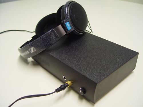
This 1 watt headphone amplifier circuit lends itself par excellence for use as driver for low impedance headphone or as output stage in a HI-FI preamplifier driving an active loudspeaker. Many preamplifiers do not permit long, unscreened leads to be connected to them, but the present amplifier accepts these happily.

| PARTS LIST | |
| R1 | 10kΩ |
| R2 | 100kΩ |
| R3 | 22kΩ |
| R4 | 100kΩ |
| R5 | 1kΩ |
| R6 | 1kΩ |
| R7 | 22Ω 1W |
| R8 | 22Ω 1W |
| C1 | 0.22µF mylar capacitor |
| C2 | 330pF ceramic capacitor |
| C3 | 1µF mylar capacitor |
| C4 | 0.1µF mylar capacitor |
| D1,D2,D3,D4 | 1N4148 |
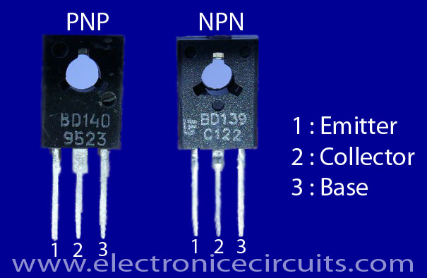
| Q1 | BD135 or BD139 |
| Q2 | BD136 or BD140 |
| IC1 | LF356 |
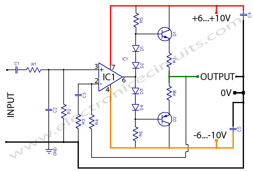
This circuit consists of an OpAmp type LF356 and a push-pull transistor output stage. Low-pass filter R1/C2 at the input limits the slew rate of the input signal. In conjunction with the relatively fast LF356, this results in very low delay distortion. The fixed quiescent current of 30mA drawn by the output transistors, and set by diodes D1 … D4 in conjunction with emitter resistors R7 and R8, ensures very low crossover distortion.
Feedback resistors R3 and R4 fix the gain at about 15dB. The consequent overall distortion with a 3 dB bandwidth from 10Hz to 30kHz is only 0.1 per cent.
The amplifier delivers a maximum power of 1 watt into 8Ω for an input signal of about 500mV rms. High-impedance headphones and 4Ω loudspeakers may also be connected with detriment.
To enable it surviving a shot circuit at the output, the two transistors should be mounted on heat sinks, do not forget the insulating washers and the conducting paste.

The power supply need not be more than a simple affair, consisting of a mains transformer with a center-tapped, 6…8V, 0.5A secondary, a suitable bridge rectifier, and two 1000µF/16V electrolytic capacitors in a conventional arrangement.
To drive high-impedance headphones at high volume, you need a ±15V regulated power supply: in some cases, this may be derived from the preamplifier supply, IN this arrangement, care must be taken not to short-circuit the output terminals.
Please send your ideas, those are very important for our success…
rare…