Skip to content
Electronic Circuits

DIY Hobby projects, diagram, schematic

Electronic Circuits

DIY Hobby projects, diagram, schematic

LED Blown AC Fuse Indicator Circuit Diagram

electronicecircuits, October 16, 2010August 15, 2023
LED Blown AC Fuse Indicator Circuit

LED Blown AC Fuse Indicator Circuit Diagram

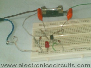
This circuit monitors a AC fuse. In this circuit, the LED indicator shows whether or not the fuse is blown.
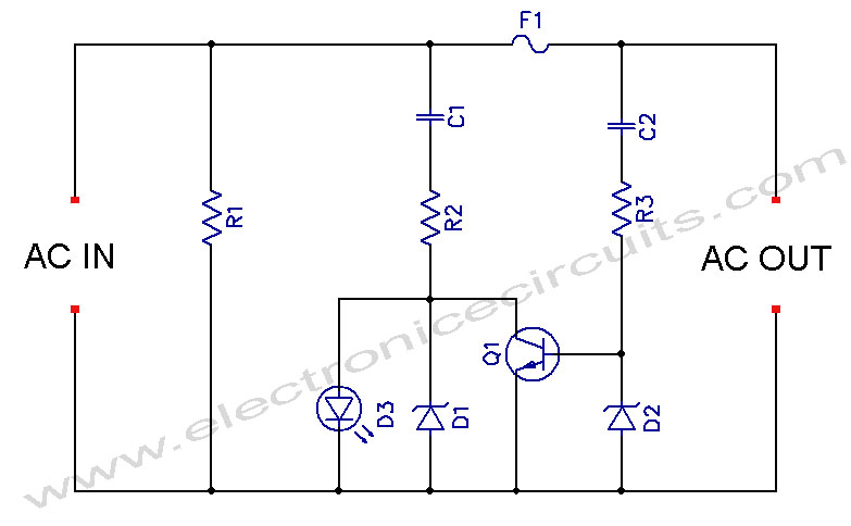
LED Blown AC Fuse Indicator Circuit Diagram

PARTS LIST
R11MΩ
R2100Ω
R31kΩ
C10.47µF 250V
C20.47µF 250V
D12.7V 0.5W Zener Diode
D25.6V 0.5W Zener Diode
D3LED
Q1BC547
F1FUSE

This  fuse indicator circuit makes an LED light up if a fuse blows, this gives a quick indication if the fuse has open and the LED can be sited on the front or rear panel saving time when fault finding.

This blown fuse detector will work with a wide range of AC supply voltages from 30V to 300V and good for use with few milliampere to many amperes fuse.

Don’t touch any component, when circuit is connected to the AC power.

LED Blown AC Fuse Monitor CircuitLED Blown AC Fuse Indicator Circuit

Please send your ideas, which are very important for our success…
Electronic Circuits Indicator Circuits

Post navigation

Previous post
Next post

Comments (3)

  1. livelybrowsers says:
    October 19, 2010 at 11:20 pm

    Thanks for good stuff

    Reply
  2. Mike Amaral says:
    August 13, 2013 at 7:33 am

    Nice, simple, useful circuit.
    Please elaborate on the purpose of R1. It appears circuit would work OK without it. Might add protection of LED and/or transistor from voltage spikes or transients?

    Reply
    1. GT says:
      November 15, 2013 at 12:38 pm

      can you please tell me what can i add to this circuit to protect LED and transistor on spikes thanks

      Reply

Leave a Reply Cancel reply

Your email address will not be published. Required fields are marked *

  • Diagrams
  • Privacy Policy
  • Software
  • Contact

Recent Posts

  • LM317 CONSTANT CURRENT CALCULATOR
  • 5V buck converter – LM2576 simple DIY project
  • ICL7107 PANEL METER
  • Precision 1Hz clock generator circuit
  • Toggle to Momentary Switch Using 555 Monostable

Categories

  • Circuit Tutorials
  • Electronic Circuits
  • Electronic Software

AC Projects Alarm Circuits Amplifier Circuits Amplifiers Antenna Circuits Battery Charger Calculator software Circuit Designer Control Circuits Converter circuits Crossover Circuits Data Sheets Digital Circuits Electronic Switch Flasher Circuits Game Circuits IC Programmer IC Programming Indicator Circuits LED Circuits Light Circuits Logic Circuits Measuring Circuits Meter Circuits Microchip Motor Circuits Music Circuits Oscillator Circuits PCB Designer PIC Power Amplifier Power Guard Power Supply PreAmplifier Circuits Radio Circuits Regulator Circuits Regulator Diagrams Regulator Schematics RF Schematics Sensor Circuits Tester Circuits Timer Circuits Transmitter Circuits Tutorials Vacuum Tube

©2025 Electronic Circuits | WordPress Theme by SuperbThemes