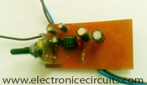
LM386 Low Voltage Audio Power Amplifier Circuit
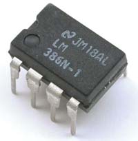
The LM386 is a power amplifier designed for use in low voltage consumer applications. The gain is internally set to 20 to keep external part count low, but the addition of an external resistor and capacitor between pins 1 and 8 will increase the gain to any value from 20 to 200. The inputs are ground referenced while the output automatically biases to one-half the supply voltage. The quiescent power drain is only 24 milliwatts when operating from a 6 volt supply, making the LM386 ideal for battery operation.
Features
- Battery operation
- Minimum external parts
- Wide supply voltage range: 4V–12V or 5V–18V
- Low quiescent current drain: 4mA
- Voltage gains from 20 to 200
- Ground referenced input
- Self-centering output quiescent voltage
- Low distortion: 0.2% (AV = 20, VS = 6V, RL = 8W, PO =
- 125mW, f = 1kHz)
- Available in 8 pin MSOP package

| PARTS LIST | |
| C1 | 220µF 16V |
| C2 | 0.047µF (473) |
| C3 | 10µF 16V |
| C4 | 4.7µF 16V |
| C5 | 1µF 25V |
| C6 | 330µF 25V |
| R1 | 10Ω |
| VR1 | 10kΩ |
| IC1 | LM386 |
| LS1 | 8Ω Speaker |
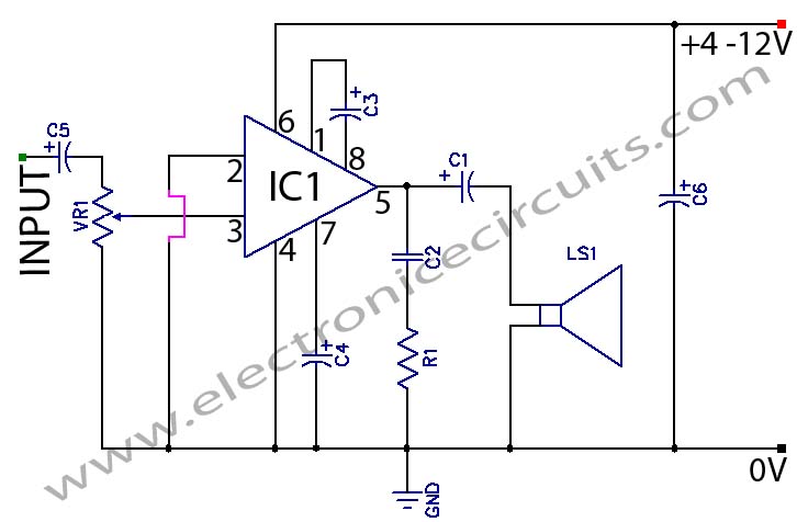
This simple amplifier shows the LM386 in a high-gain configuration (A = 200). For a minimum gain of 20, leave out the 10 uF capacitor connected from pin 1 to pin 8. Gains between 20 and 200 may be realized by adding a selected resistor in series with the same 10 uF capacitor.(when adding 1.2kΩ resistor series with C3 capacitor, gain reduce to 50. )

A small electrolytic or tantalum cap of a few uF from pin 7 to ground will isolate the high gain input stage of the LM386 from power supply noise, hum, transients, etc.Such a bypass cap is much more effective in this case. Most commercial rigs (and kits) using the LM386 either fail to bypass pin 7 at all or use too small a value (0.01uF or 0.1uF) to be totally effective and increasing the value to 4.7uF completely eliminates the “thumps” in the audio output produced by Vcc transients when the transmitter is keyed.

Please send your ideas, those are very important for our success…
SIR,
MY DAUGHTER IS DEAF WITH 80 DB LOSS.
WILL YOUR EQUIPMENT WILL SERVE ANY PURPOSE FOR HER ?PLEASE SUGGEST.
what’s other capacitors working????
i want to know advantages and disadvantages of the portable audio amplifier .can u please tell me