Low resistance measuring meter circuit
The low resistance meter circuit described here is simple and has the following advantages over other meters:
* No zero knob (see it once and forget it forever).
* Scale reading is from zero to a fixed value rather than infinity.
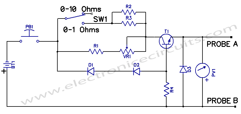
* LRMM uses a 1.5-volt penlight cell, two scales (0-1 ohms and 0-10 ohms) over a dial and a push-to-on switch due to large power consumption by the circuit.

| PARTS LIST | |
| R1 | 27Ω |
| R2 | 3.3Ω |
| R3 | 3.3Ω |
| R4 | 330Ω |
| VR1 | 100Ω |
| D1 | IN4001 |
| D2 | IN4001 |
| D3 | IN4001 |
| T1 | BC147B |
| BT1 | 1.5V CELL |
| PV1 | 500µA AMMETER |
| PB1 | PUSH TO ON SWITCH |
A constant current generator T1 passes a known current through the resistance to be measured. A maximum drop of 100 mV across the emitter of T1 and ground is displayed on the meter whose internal resistance is much higher than the testing resistance (maximum 10 ohms), due to which the meter does not load the circuit. The diode across the absence of a testing resistance.
The bias for the transistor is provided by R1, VR1, R2, R3, D1, and R4. Using diodes D1 and D2 helps in holding the bias level constant, disregarding of decaying battery.
The meter should have a 0-500µA linear scale. Any general-purpose meter can be used with a shunt resistance. T1 can be any silicon NPN transistor with a high current gain factor.
Adjust the instrument by shorting probes A and B. Otherwise it shows a zero resistance. Adjust in 0-10 ohms scale first. Other adjustments follow automatically. This circuit can be easily built within an hour.
Please send your ideas, which are very important for our success…
thanks, and maintain up the good work
thanks, and keep up the great work
Nice one ..great project for the electronics beginers