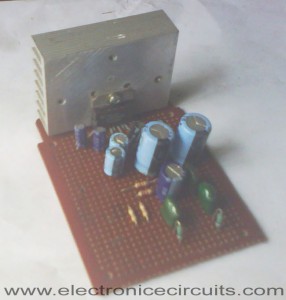
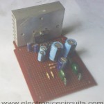
TDA2004 Car Battery 12W Stereo Amplifier Circuit
Its main features are :
Low distortion.
Low noise.
High reliability of the chip and of the package with additional safety during operation thanks to protections against :
- OUTPUT AC SHORT CIRCUIT TO GROUND
- VERY INDUCTIVE LOADS
- OVERRATING CHIP TEMPERATURE
- LOAD DUMP VOLTAGE SURGE
- FORTUITOUS OPEN GROUND
Space and cost saving : very low number of external components,very simple mounting system with no electrical isolation between the package and the heatsink.
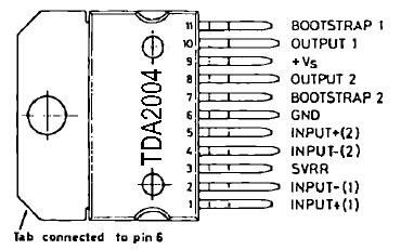
The TDA2004A is a class B dual audio power amplifier in MULTIWATT package specifically designed for car radio applications.
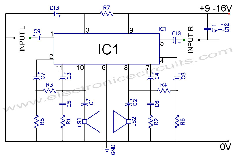
| PARTS LIST | |
| R1 | 1Ω |
| R2 | 1Ω |
| R3 | 1.2kΩ |
| R4 | 1.2kΩ |
| R5 | 3.3Ω |
| R6 | 3.3Ω |
| R7 | 120kΩ |
| C1 | 2200µF 16V |
| C2 | 2200µF 16V |
| C3 | 100µF 16V |
| C4 | 100µF 16V |
| C5 | 100nF (104) |
| C6 | 100nF (104) |
| C7 | 220µF 16V |
| C8 | 220µF 16V |
| C9 | 2.2µF 16V |
| C10 | 2.2µF 16V |
| C11 | 100nF (104) |
| C12 | 470µF 25V |
| C13 | 10µF 16V |
| LS1, LS2 | 4Ω 10W speaker |
| IC1 | TDA2004 |
With the component values shown and with a supply voltage of 14.4V (a fully charged car battery), the stereo amplifier is capable of delivering a power output of at least 6W, typically 6.5W with a load impedance of 4Ω. It can also handle a load impedance of 2Ω, in which case the output power is a minimum of 9W, but typically 10W. Power outputs of this order are subject to about 10% distortion, however, if lower power outputs are acceptable, 4W with a load impedance 4Ω or 6W with a load impedance of 2Ω, distortion is only in the order of 0.3%.
The voltage gain of the left-hand channel is determined by the ratio of R3 to R5, and that of the right-hand channel by the ratio of R4 to R6. With the values given, this will be 50dB. Therefore, a signal of 50mV is required at the input to give the maximum output. If this input sensitivity is too great, a 50kΩ stereo potentiometer can be included at the input. The impedance of non-inverting amplifier input is minimally 100kΩ.
The network consisting of resistor R1 and capacitor C5 (and R2, C6) is included to prevent the amplifier oscillating at high input frequencies. The bandwidth of the circuit is more than adequate for use as a car radio amplifier. The frequency response of amplifier is 40Hz to 16kHz (3dB points).
The IC must be kept sufficiently cool. The thermal resistance of the heatsink should be at least 4°C/W.
Please send your ideas, which are very important for our success…
I appreciate for your info…
that something i whant to as about the TDA2004 Car Battery 12W Stereo Amplifier Circuit….
this capacitor 2200uf 63v in c1,c2…can use 2200uf 16v….
Can we operate TDA 2004 at low current (about 1.3A) with low voltage 12V . if yes what i have to do to get better output? and one more question can what will happen TDA input are shorted and mono tone is send ?
can you send pcb layout
GETTING GROUND LOOP HOW DO I FIX THIS
tda 2004 is the best amplifier 🙂
How to remove noise??????