
Crystal Controlled Oscillator Circuit
This general purpose signal source serves very well in signal-tracing applications. The output level is variable to more than 1 Vrms into a 50Ω load. Almost any crystal in the 1 to 15 MHz range can be used.

| PARTS LIST | |
| R1 | 10kΩ |
| R2 | 10kΩ |
| R3 | 10kΩ |
| R4 | 10kΩ |
| R5 | 2.2kΩ |
| R6 | 470Ω |
| R7 | 33Ω |
| R8 | 500Ω Preset |
| C1 | 0.001µF (102) |
| C2 | 100pF |
| C3 | 0.001µF (102) |
| C4 | 0.01µF (103) |
| C5 | 0.01µF (103) |
| C6 | 0.01µF (103) |
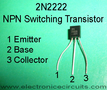
| Q1 | 2N2222 |
| Q2 | 2N2222 |
| XTAL1 | CRYSTAL (1 to 15 MHz) |
Q1 forms a Colpitts oscillator with the output taken from the emitter.
A capacitive voltage divider (across the 2.2k Ω emitter resistor) reduces the voltage applied to the buffer amplifiers Q2. The buffer and emitter follower, provides the low input impedance necessary to drive 50Ω loads.
 |  |  |
Please send your ideas, which are very important for our success…
Very good, but too much components, when compared to a NE555 based oscillator. But it’s ok, as the output frequency is fixed and cannot be changed here.
I agree there are a little more components than the other form but for someone who is learning electronics from the start I found this to be quite doable.
I agree there are a little more components than the other form but for someone who is learning electronics from the start I found this to be quite doable.
I built this circuit verbatim but can only get 500mV PP output at 10 MHz. I was hoping it would work at 1000KHz, the best I could do was get it to oscillate at 1400KHz. Any comments?