
4017 LED Knight Rider Running Light Circuit Diagram
In this 4017 Knight Rider circuit diagram, the 555 uses as an oscillator. It can adjust to give the desired speed for the display. Because the output of the 555 is directly connect to the input of a Johnson Counter (CD 4017).

| PARTS LIST | |
| R1 | 22kΩ |
| R2 | 220Ω |
| VR1 | 50kΩ PRESET |
| C1 | 1µF 16V |
| C2 | 0.01µF (103) |
| C3 | 10µF 16V |
| D1 – D10 | 1N4148 |
| D11 – D16 | LED |
| IC1 | NE555 |
| IC2 | CD4017 |
The input of the counter is called the CLOCK line. The 10 outputs become active, one at a time, on the rising edge of the waveform from the 555. Each output can deliver about 20mA but a LED should not be connect to the output without a current-limiting resistor (220Ω in the circuit above).
CD4017 pinout and description
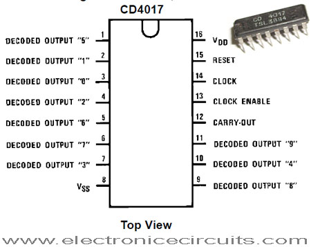
The first 6 outputs of the chip connect directly to the 6 LEDs and these “move” across the display. The next 4 outputs move the effect in the opposite direction and the cycle repeats. The animation above shows how the effect appears on the display.
Also using six LEDs, the display can be placed in the front of a model car to give a very realistic effect.
The outputs can be taken to driver transistors to produce a larger version of the display.
 |  |
4017 LED Knight Rider Circuit Video
Please send your ideas, which are very important for our success…
Hi Great project . but where dose pin 3 go from 555 timer to 4017 ? and GND from 4017 all so how do i add more than 6 leds ? thx
[img]night rider circuit pcb[/img]
555/no 3 go 4017/no14, GND 4017/ no 8.13.15
Mandami lo schema elettrico del cd4017 a 6 led come supercar, con i suoi valori giusti,
per funzionare il circuito, mandami un e-mail
3rd Pin will go to 14th Pin of 4017IC.. & 8, 13, 15 PIN will be shorted…. You have to give power Supply on 16th PIN… Hope your problem is solved.!!
wow.. man…. itz nicely working.. maxxa.. thnx a lot..
is it working as the real knight rider?? I mean LEDs going fade?
hi.tanks
Mandami lo schema elettrico knight rider come supercar
hi there, what part to change if i want use power supply 12v dc,… thanks
ware nic led caiuet
maxxa. its really work!!
Nice. working excellent. thx
Dear friend
Pls send two LED bulb circuit(robo circuit) daigram.
Where is pin 12th of ic4017 Is connected?