
Automatic Gain Control PreAmplifier Circuit Diagram
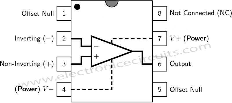
The preamp circuit uses an easily obtained 741 op amp set for an internal gain about 200.

| PARTS LIST | |
| R1 | 100kΩ |
| R2 | 470Ω |
| R3 | 10kΩ |
| R4 | 10kΩ |
| R5 | 560kΩ |
| R6 | 100kΩ |
| R7 | 10kΩ |
| R8 | 10kΩ PRESET |
| R9 | 100kΩ |
| C1 | 1µF 16V |
| C2 | 1µF 16V |
| C3 | 10µF 16V |
| C4 | 1µF 16V |
| C5 | 0.1µF (104) |
| C6 | 10µF 16V |
| C7 | 0.22µF (224) |
| D1 | 1N4148 |
| D2 | 1N4148 |
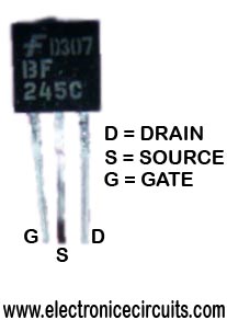
| Q1 | BF245 |
| IC1 | LM741 |
A portion of the op amp’s output signal is rectified by the 1N4148 diodes, then filtered and fed to the gate of the FET input shunting circuit. As the output rises, more and more input shunting takes place. That is, more of the input signal is bypassed, effectively keeping the output level constant.
This preamp circuit offers a 100:1 limiting action. The input level can change over a 100:1 ratio with little or no effect on the output level.
The output output level itself can be set from less than unity all the way up to nearly the gain of the amplifier, making the circuit usable in other applications as well.
 |  | |
Please send your ideas, which are very important for our success…
tanks for sending
very good
Please send me your Automatic Gain Control PreAmplifier Circuit Diagram.Thanks.
good
Hei!
Is there a way how to calculate all the necessary element values? Or it’s done just by trying? Thanks!
Can the electrolytic caps be MMLC instead?
hello , can you suggest me the replacement or subtitute the FET BF 245,,,no available this kind of transistor in our place,Please reply me soon,
Hoping your kind consideration regarding this matter,
Thanks,
AWEGFAWER
We have tried the circuit, but it does not function as AGC. It could produce sound , maybe its pre-amp circuit works fine. what could be the problem?
Thanks a lot
ok very good
what does this means what is the exact specification on the these two capacitor 0.22µF (224)
and 0.1µF (104).
there is a book named FORST MIMMS mini note books
THE OPAMP 741 1458 AND OTHERS
THERE IS A PAGE ON CALCULATEING THE GAIN
P.S.radio shack sold the book long ago