555 Negative Voltage Power Supply Circuit
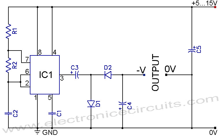
A negative supply can be generated by a “Charge-Pump” circuit created with a 555, diodes and capacitors.
Another advantage of this circuit is that, the negative voltage together with the original positive supply can be used to simulate a dual supply. This circuit diagram shows how to obtain a negative voltage from a positive voltage supply.

| PARTS LIST | |
| C1 | 0.1µF (104) |
| C2 | 0.022µF (223) |
| C3 | 22µF 25V |
| C4 | 33µF 25V |
| C5 | 100µF 25V |
| R1 | 4.7kΩ |
| R2 | 33kΩ |
| D1 | 1N4002 |
| D2 | 1N4002 |
| IC1 | NE555 |
The 555 is connected as an astable multivibrator operating at around 1KHz. During the timer output at pin 3 goes positive, the series C3 capacitor charges through the diode D1. When the output switches to ground, the C3 cap discharges through the D2 and charges the C4 capacitor to a negative voltage. As a result of this the voltage at the junction of the anode of D2 and cathode of C4 will be always negative with respect to the ground. The output will deliver about 50mA.
Please send your ideas, which are very important for our success…
With DC and positive voltage signals the current goes from source to ground now with AC you have negative voltage how does current travel then? Current also travels from the ground to the source thru a positive voltage except it is the negative current. So to your question a negative voltage can have either negative current or positive current flowing thru it.
It as simple as charging capacitor and then on second phase of generator passing the charge to the other capacitor. The voltages sum up on charge-discharge phases. The funny part is that diodes work here as switches to perform charge-recharge cycles, but they also cause inversion of the voltage by doing this. It is easy to imagine how it works by thinking of cpacitors as charged batteries and then trying to imagine switches and changing polarity of two batteries.
1. C3 is charegd positively on high level/voltage from 555 output because D1 is conducting current and D2 is cut off.
2. 555 output goes to 0V and pulls C3 + to zero. Therfore D1 has negative voltage (polarity change) now and it is cut off while D2 opens (conducts) so the charge is passed to C4. But C4 gets the charge in opposite polarity hence creating relative negative voltage.
3. Cycle repeats.
D4 is always getting charged in relative (to 0V) negative polarity then it is always negative voltage. It can be dischared only by output load.
What would the output voltage be if you feed in a 15V DC supply? My guess is that through the internal resistance of the IC, resistors and the capacitors, there will be a great loss of Power. When you specify that the max input voltage 15V is, then the output will be more than -15V. How would you manage to get a output Voltage supply of exactly -15V?
Loss is also due to diodes (0.7 V on each). I am not sure if are able to build it like this with this simple pump. I would assume voltage to be up to 2 volts lower than power delivered to 555 (probably around 13 Volts if positive voltage to convert from is 15V).
Can I increase current deliver up to 100-200Ma?
Yes you can. It is limited by pumping by output efficiency of 555 (output max current). If you use additional output power transistor base (for bipolar transistor) connected to pin 3 in proper configuration with emmiter transistor or some B class two transistor simple power amplifier then you can pump more current and hence increase power/coutput current (continuous).
This style of power voltage inverting was used in RS-232 interface circuits like old MAX232 where you had only one positive voltage available (eg. TTL powered 5 volts) and you needed bipolar signal following the standard specification.
There is also a way to multiply voltage like this, but current would be dropping.
If i give 5V input then what will be the output voltage?