Skip to content
Electronic Circuits

DIY Hobby projects, diagram, schematic

Electronic Circuits

DIY Hobby projects, diagram, schematic

1.5v One Battery LED Light Flasher Circuit Diagram

electronicecircuits, December 14, 2010August 15, 2023
1.5v One Battery LED Light Flasher Circuit

1.5v One Battery LED Light Flasher Circuit Diagram

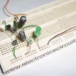
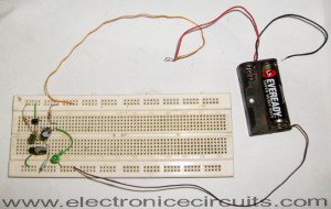
This will flash a LED, using a single 1.5V or 1.2V cell.
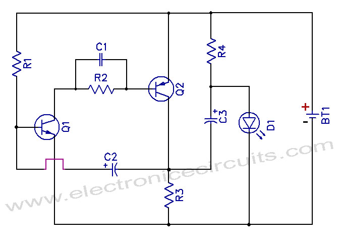
1.5v One Battery LED Light Flasher Circuit schematic

PARTS LIST
R1100kΩ
R21kΩ
R347Ω
R410kΩ
C10.01µF (103)
C210µF
C3100µF
Q1BC547
Q2BC557
D1LED
BT11.2V or 1.5V Battery

It will even flash a white LED even though this type of LED needs about 3.2V to 3.6V for operation.

Note the R4 in series with LED charges the C3. It does not illuminate the LED. When the two transistors conduct, the collector of the Q2 rises to rail voltage and pulls the C3 high. The negative of the C3 effectively sits on top of the positive rail. All the energy (BT1 + C3) is pumped into the LED to flash.

The circuit takes about 2mA but produces a very bright flash.

You can adjust flash rate changing R1.

1.5v One Battery LED Light Flasher Circuit1.5v One Battery LED Flashlight Circuit Diagram

Please send your ideas, which are very important for our success…
Electronic Circuits LED Circuits

Post navigation

Previous post
Next post

Comments (4)

  1. anon says:
    December 17, 2010 at 2:13 am

    Flasher as in a blinky thing?
    I mean, the LED flashes on and off or?

    Reply
  2. pharmacy tech says:
    December 27, 2010 at 8:06 am

    found your site on del.icio.us today and really liked it.. i bookmarked it and will be back to check it out some more later

    Reply
  3. p.Subramaniyam says:
    October 29, 2014 at 4:05 pm

    Good. Am interesting electronic pls send me more

    Reply
  4. Dan Smith says:
    March 26, 2015 at 6:21 am

    Great article, very detailed and good drawing of circuit. Any idea what the total current flow is in between LED flashes?

    Reply

Leave a Reply Cancel reply

Your email address will not be published. Required fields are marked *

  • Diagrams
  • Privacy Policy
  • Software
  • Contact

Recent Posts

  • LM317 CONSTANT CURRENT CALCULATOR
  • 5V buck converter – LM2576 simple DIY project
  • ICL7107 PANEL METER
  • Precision 1Hz clock generator circuit
  • Toggle to Momentary Switch Using 555 Monostable

Categories

  • Circuit Tutorials
  • Electronic Circuits
  • Electronic Software

AC Projects Alarm Circuits Amplifier Circuits Amplifiers Antenna Circuits Battery Charger Calculator software Circuit Designer Control Circuits Converter circuits Crossover Circuits Data Sheets Digital Circuits Electronic Switch Flasher Circuits Game Circuits IC Programmer IC Programming Indicator Circuits LED Circuits Light Circuits Logic Circuits Measuring Circuits Meter Circuits Microchip Motor Circuits Music Circuits Oscillator Circuits PCB Designer PIC Power Amplifier Power Guard Power Supply PreAmplifier Circuits Radio Circuits Regulator Circuits Regulator Diagrams Regulator Schematics RF Schematics Sensor Circuits Tester Circuits Timer Circuits Transmitter Circuits Tutorials Vacuum Tube

©2025 Electronic Circuits | WordPress Theme by SuperbThemes