
CD4060 Timer Circuit 1 minute to 2 hours
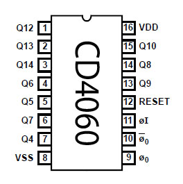
This is a 1 minute to two-hour timer switch. The 14-stage binary ripple counter Type 4060, IC1, has an on-chip oscillator capable of stable operation over a relatively wide frequency range. Therefore in the present 4060 timer circuit, the oscillator frequency determine by an external RC network connected to pins 9, 10 and 11.

| PARTS LIST | |
| R1 | 2.2MΩ |
| R2 | 18KΩ |
| R3 | 1KΩ |
| R4 | 1KΩ |
| R5 | 1KΩ |
| R6 | 1MΩ |
| VR1 | 500KΩ (504) |
| C1 | 220nF (224) |
| C2 | 10nF (103) |
| D1 | LED |
| D2 | LED |
| D3 | 1N4001 |
| Q1 | BC547 |
| IC1 | CD4060 |
| RL1 | Relay |
When the power is on, the pulse at junction R6-C2 resets the counter and counting starts. When the counter reaches bit 14 (Q13), pin 3 goes high so that the relay, a 9V type, is turned on via driver Q1.
Features – Wide supply voltage range: 1.0V to 15V, High noise immunity: 0.45 VDD (typ.), Low power TTL compatibility: Fan out of 2 driving 74L or 1 driving 74LS, Medium speed operation: 8 MHz typ. at VDD = 10V, Schmitt trigger clock input.
The time delay can set using with the aid of VR1. Also time delays of between one minute and two hours are possible by appropriate dimensioning of the timing components:
1-30 minutes: C1 = 220nF ; VR1 = 500KΩ.
1-60 minutes: C1 = 470nF ; VR1 = 500KΩ.
1-120 minutes: C1 = 470nF ; VR1 = 1MΩ.
9V PP3 battery uses to power this 4060 timer circuit. Light-emitting diode D1 does not affect the operation of the circuit. Because D1 include merely to show that the timer works. Diode D1 and resistor R4 are , therefore, optional components.
 |  |
Please send your ideas, which are very important for our success…
very well
thanks 4 all
i am a very fresh guy for electronics. i tried to get the parts to try this circuit but the shopkeeper is asking the voltage for 220nF (224) & 220nF (224) capacitors. and also what is given in brackets for nf capacitors and VR1500KΩ (504)
thank you brother for your circuit.
the capacitors you may use are not electrolytic but common capacitors (ceramics) These capacitors they (often) have no voltage limit and aren’t polarized….
VR=Variable Resitor wich actually is any potentiometer or trimmer
Hello, Could you advise a suitable alternative to the BC547 transistor, which seems to be temporarily unavailable in the UK. I do have some BC548B transistors, will they work OK. Thanks.
plz dont forget me Ineed more
thank for Electronic Circuits
Nice circuit! I’m looking forward to make one timer like this, Thanks!
In this circuit one led continously blinking and other LED blinks for some times ,but the supply given to the device will not cut off,whats the problem
To Jeevan, try using 16v capacitors or higher
Hi,
I want a timer which can work for 10 hour. please suggest
thanks dear
i want cct a 3 sec “on” & 4 min “off”.it will work 24 hrs,can u send me a one it will big help to me,thank’s bro,
palitha,,,,,,,,,,,,,!
thanks for circuit
very nice ..thankuu
Thank you for a nice video.
I have been trying with the 555 timer but I would need an “on” time of only one second, and a “off” time of 20 minutes. (or reverse), Is this possible with the 4060?
Many thanks
how if i want to select 1minute? change the value of capacitor or what i should do??
Very very nice cct. Thank u……
nice one..i got it,, i put 3 ceramic capacitor fot a long delay
nice man…i got it
Thanks to you sir for CKT.
sir,, please say what is the output voltage??
Hai this ir circui is almost work my idea is laser security system please send for my gmail to the circuit
Circuit works but not the reset wit 0.1uf and 100k
You have an idea?
VERY WELL THANKS FOR ALL
UR CIRCUIT IS GOOD. THANKS FOR UR KNOWLEDGE SHARING.
one thing i would like to know about the circuit,
let as assume that the counter is started and then we are disconnecting the battery, then we are connecting the battery again.
now my doubt is at this stage whether counter will reset or continue from the dropped point
THANKS I am good in electronics but I want to make this circuit in practice but I want to looking for internal structure of this integrated circuit really I need ur opinion
of course I would like to know the internal structure of CD4060 TIMER CIRCUIT
what should i change in circuit for dont repeat a timre after complete timer & lock the output…i dont want to repeat the timer… please help.. i dont know this oscillator properly…
Hi — Hope you are still looking at this, I built the circuit as described and for the delay time it works perfectly, however after about the same amount of time as the delay time, it turns off and cycles like that. Delay 1 minute, relay goes on, wait another minute and it turns back off (pin 3 goes low), and this repeats, any idea on what I might have wrong or what I can do to keep it from turning back off?
Thank you for your time and the circuit.
hai
I have 20 led lights powered by 4aa (6v) batteries with a on off button. I would like the light to delay for 1 hour before it goes on.
very nice circuit , Thank you
VVI circit.
very use full circuit for me THANKYOU sir….
I am manoj like the electronic
thanx ma friend for this knowledge you have given to me
What is the relay for, it doesn’t seem to be used at all.
Nice and simple circuit. Thank you
What is the capacitor of 470nf , details please
i wann to work time delay off only using rasistor & capacitor can you help me thanks
If we need a time delay of 24 hours, can we use the same ic for it? if so how to do it?
hi, i have 3 questions
1.how long the bell or any device to relay will ring?
2.this circuit will automatically start counting after its first perfomance?
3.is it possible to regulate 3 minutes?
PLEASE UR ANSWERS IS HELP FOR US AS USUAL
verythanks
sir i want a circuit works on same concept but just for one cycle means when i activate the circuit its change the relay state only for once please help
this tutorial video is it for this circuit truly coz the components values are different according to the circuit diagram shown before the starting