Discrete Class AB Transistor Audio Power Amplifier Circuit Diagram
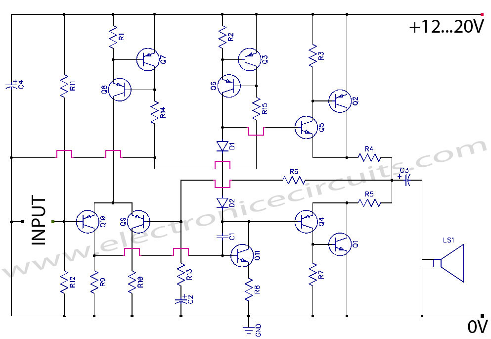
This is a class AB transistor power amplifier. It is a simple amplifier to build, uses standard parts and is stable and reliable. The entire circuit utilizes commonly available components and may be simply built over a general-purpose board. But this amplifier has very good sound quality.

There are eleven transistors, including four in the output stage. Q1 and Q2 transistor must be between 3 and 5 amperes power transistors. Q4 and Q5 must be between 100mA and 500mA driver transistors. Other transistors are 10mA small driver transistors. Q1, Q4 and Q2, Q5 are complementary pairs, they make complementary darlington pairs.
| PART LIST | |
| R1 | 1.5KΩ ¼W |
| R2 | 150Ω ¼W |
| R3 | 1KΩ ¼W |
| R4 | 0.22Ω 2W |
| R5 | 0.22Ω 2W |
| R6 | 39KΩ ¼W |
| R7 | 1KΩ ¼W |
| R8 | 120Ω ¼W |
| R9 | 6.8KΩ ¼W |
| R10 | 6.8KΩ ¼W |
| R11 | 47KΩ ¼W |
| R12 | 47KΩ ¼W |
| R13 | 2.2KΩ ¼W |
| R14 | 180KΩ ¼W |
| R15 | 18KΩ ¼W |
| C1 | 22pF Ceramic |
| C2 | 4.7µF 16V |
| C3 | 1000µF 25V |
| C4 | 100µF 25V |
| D1 | 1N4148 |
| D2 | 1N4148 |
| Q1 | 2SD313 |
| Q2 | 2SB507 |
| Q3 | 2SA733 |
| Q4 | 2SB560 |
| Q5 | 2SD400 |
| Q6, Q7, Q8, Q9, Q10 | 2SA733 |
| Q11 | 2SD400 |
| LS1 | 4Ω 20W SPEAKER |
Power output of the amplifier
| Supply voltage (Vs) | = 20V |
| Speaker impedance (R) | = 4Ω |
| Peak to peak voltage (Vpp) | = 20-2 =18V |
| Peak voltage | = 9V |
| Maximum output (Pmax) | = 9V2/2R |
| = 81/8 | |
| = 10W |
10W is much enough for the day today home usage.
Amplification of this amplifier (A)
| A | = R6/R13+1 |
| = 39KΩ/2.2KΩ+1 | |
| = 18 |
Volume control can add to the circuit by connecting a 10KΩ POT in series to the input of the amplifier.
Q1 and Q2 must be kept sufficiently cool, so it is mounted on a suitable heat sink. If you used single heat sink please use insulation between transistors and heat sink.
Please send your ideas, which are very important for our success…


This is a neat and simple circuit. It should be easy to build and will work great.
thanks
oh!awesome!
(Portuguese From Brazil) que maravilha esses progetos eu realmente amei são fáceis e praticos
Nós do Brasil escrevemos pro”G”eto com “J”! Enfim, o projeto é sim muito bom. Vou montar e avaliar e comparar com o TEA2025B, que é o padrão para caixas de computador. O objetivo é construir um amplificador básico com ótimas respostas para o dia-a-dia na frente do computador.
i just want to ask,, where did they got the value of 2 in solving the voltage peak to peak???
nice
i am using MS2475 transistor in my design but unfortunately this transistor is not easily available.so any one can tell me about its replacement.i am designing my amplifier in ADS .any one know any thing about it .contact me .thanks
Nice, very nice!
thank you very much
AS A PRACTICAL
is it ok to use 5watts in a resistor .22ohm rather than a 2 watss resistor?
Hi guys,
If you are beginner and want to build your own amplifier circuit then visit this link to watch this video and have your complete kit for building your great tda2030a / tda2050 based stereo amplifier.
https://www.youtube.com/watch?v=Lmi8B26XEG4