
L200 12V Constant Voltage Battery Charger Circuit
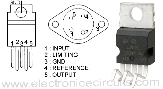
This battery charger is based on L200 regulator IC. L200 is a five pin adjustable voltage and current regulator IC.
This regulator IC is used to keep the charging voltage constant up to maximum charging current. After exceed this limit drop charging voltage and maintaining maximum charging current.

| PARTS LIST | |
| R1 | 820Ω |
| R2 | 0.47Ω 3W (see texts) |
| R3 | 1.8kΩ |
| R4 | 1kΩ Preset |
| C1 | 470µF 35V |
| C2 | 0.1µF (104) |
| D1 | 1N4148 |
| D2 | 1N5401 |
| PV1 | 2 ampere meter |
| IC1 | L200 regulator IC |
R4 preset is used to control the charging voltage. You can set it to maximum battery voltage.
R2 3W resistor is used to control the maximum charging current (I).
I=0.45/R2 (R2 should be larger than 0.225Ω)
You can adjust “I” up to 2A.
example: when you using 0.47Ω resistor
I=0.45/0.47
I=0.95
I≈1A
The L200 design allows some leakage from cells connected while the circuit is not powered. D1 prevents this loss and protects the circuit from reverse polarity.
The L200 needs an input voltage that is at least 2v higher than the output to be able to yield the full rated output. You also need sufficient volts to cover the forward voltage drop of D1. With a 0.6V D1 drop, the input to the L200 needs to be 2.6V higher than the desired output.
You can use 18V 3A transformer and 3A full wave rectifier or bridge rectifier for power supply.
The L200 must be kept sufficiently cool, because it is mounted on suitable heat sink.
 |  |
Please send your ideas, which are very important for our success…
good project
interesting, thanks
salam bhai.i apreciat that u r a intelligent and also pray for u that Allah help u more education.
yar ye battery ko kis level par cut of kare ga r last low level tak kaha charging le kr jay ga ye circuit r ap kaha k resedent hain kindly tell my yahoo id thanks
i’m making a 12v vehicle charger for Mobile devices. and i want to adjust the voltage/ current to 5v / 250ma and this one is very helpfull for me.
thank you for sharing.
can this be use to charge 12v 200ah deep cycle battery
can i use this circuit for charging 12v & 7.5ah battery of ups ?
I need to know is there is any SMD package available in L200 and also how much effect …if it is possible use LI ON batteries