
Infrared (IR) Remote Control Tester Circuit
This is a simple IR tester circuit you can build in order to test infrared remote controls. The circuit uses an IR photo-transistor (IR1) to detect a remote control’s IR output signal.

| PARTS LIST | |
| R1 | 10kΩ |
| R2 | 1kΩ |
| R3 | 1MΩ |
| VR1 | 1MΩ Preset |
| VR2 | 10KΩ Preset |
| C1 | 0.01µF (103) |
| C2 | 1µF 16V |
| C3 | 10µF 16V |
| C4 | 220µF 16V |
| IR1 | Infrared Photo-Transistor |
| LS1 | 8Ω 0.5W Small Speaker |
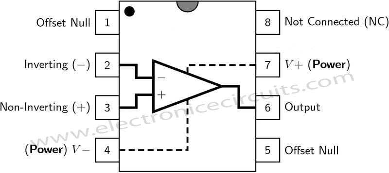
| IC1 | LM741 |
| IC2 | LM386 |
This circuit is designed to demodulate amplitude-modulated (AM) IR light beams will drive a speaker.

LM741 is amplified the IR1 signal and LM386 is driven the speaker.
VR1 is used to control sensitivity and VR2 is used to control the volume of speaker (LS1)
The Speaker will sound when any of the Remote-Control pushbuttons will be pressed.
This circuit tests consumer electronic hand held remote controls such as those used by TVs, VCRs, DVD players and more.
 |  |
Please send your ideas, which are very important for our success…
this post is very usefull thx!
I just signed up to your blogs rss feed. Will you post more on this subject?
this was a really nice post, thanks
well we can receive signals just by tuning our radio(AM) while pressing the remotes button do we ? but it gives only simple beep beep noise ,,,coz some times i does that when ma tv s remote control get upset !!! thanks
how can we drive a motor using output of this?
Yes very good
Thanks a lot. Made this. Works well. But AA batteries can’t give enough power and work a bit of time. Connected it to power supply. Wait for other cool stuff.