
LM317 Battery Charger Circuit
According to the battery manufacturers, a battery should be charged with only 1/10 current (in ampere), of its Ah value.
For example, if a battery is of 7Ah value, then it should be charged with 0.7 Ampere current. Charging a battery using this rule, extends the battery life.

| PARTS LIST | |
| R1 | 0.56Ω 5W |
| R2 | 470Ω |
| R3 | 120Ω |
| R4 | 100Ω |
| VR1 | 220Ω |
| D1 | 5A Diode Bridge |
| C1 | 1000 µF 50V |
| C2 | 0.22 µF |
| C3 | 0.22 µF |
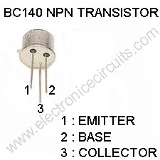
| T1 | BC140 |
| IC1 | LM317 |
| T1 | Secondary 15V, 3AMP Transformer |
| Other | Good Heat sink |
LM317 Regulator IC Pin Configuration
- Charging current is controlled by T1, R1, and R4. VR1 is used to set the charging current.
- As the battery gets charged, the current flowing through the R1 increases. This result in increase in the current and voltage from the LM317.
- When the battery becomes fully charged, charger reduces the charging current to the battery, and the battery is charged in trickle charging mode.
- The input at LM317 should be around 3 volts higher than the output voltage from the LM317. As this IC requires minimum 3-volts for its operation.
- As this IC gets very hot during operation, a good heat sink should be used with this IC.
Please send your ideas, those are very important for our success…
i think it would be more clear if you explain the working of T1,R1,R4 as current limitors.
thanking you.
awaiting your explanation
When the battery is connected, current flows through R1 and Voltage is drops accross it. This voltage now becomes the base voltage for the transistor, if this voltage exceeds about 0.7 volts, the transistor turns on and reduces the output voltage of the regulator which also reduces the charging current. Note that the higher the output voltage above the battery, the higher the charging current and the lower the output voltage of the regulator above the battery voltage, the lower the charging current. Hope this helps a little.
Can u explain it in more detail? And how can we add charging indicator for low charge and full charge indication?
Can you please explain me the above circuit
Good, can you tell how to lmprove it for hire rating. Thanks
Right, this is usefull for SLA charge long time without broken. because T1-BC140 will be open close-up, it’s protect over current for LM317 at full-charge, that’s meaning limited current for SLA battery. add diode (1N4007) input and out put to wrong plug-in power pole.
Thanks for posting this circuit. It’s a great reference.
How can I calculate the max charging current using VR1?