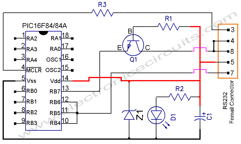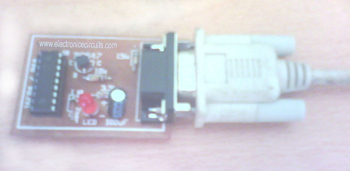
PIC Programmer Circuit diagram
Following uJDM PIC programmer circuit is a circuit which suitable to do simple pic16f84, pic16f84A, 16c84, 16f628 group programmer.

| PARTS LIST | |
| R1 | 10KΩ |
| R2 | 3.3KΩ |
| R3 | 15KΩ |
| C1 | 100µF 16V |
| D1 | LED |
| Z1 | 5.1V Zener |
| Q1 | BC547 |
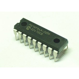
| PIC | PIC16F84,PIC16F84A, 16C84, 16F628 |
| Rs232 | RS232 Femail Connector |
| IC Base | 18 pin ic base for PIC |
BC547 Transistor Pin Configuration
- Using IC base for PIC
- Connect the PIC programmer to 1st or 2nd COM PORT of computer by using RS232 wire.
- USE MPLAB AND IC-PROG (or any ic programming software) to program PIC with this PIC Programmer.

PIC PROGRAMMER

lease send your ideas, which are very important for our success…
you guys are great, thanks for helping me out!
thinks, but do i have to use a RS323 cable, i did make this circuit , but i used a femelle db9, directlly to my com port
do the led have to light up, when i connect my boadr to the comport , or she indecate the reading and writing operation, how i can configurate my ic prog ??
very thanks, but I cannot fing PIC ic’s in local store
I like progemms with pic16f84a pleszzz tch me web seit plezz
Wow … its a very simple thing. thanks, what a great share
Its very nice to get help from a SRI LANKAN website. 🙂
thanx again and again.
Hello,
Can I connect this nice programmer to an USB port with an adapter?
aim going to build my own programmer from here LOL but i want to look to project working good because i had buy the componements of this programmer. Thanks bro for your help!
Thanks to you, it’s excellent .
hello,
its really good and helpful for the person, who learn the circuit.
tell how will do the programming through my pc? is it possible and yes then how?
mineshkumar
actually i want a circuit diagram of the line follower based on 16f84a so any one have then please send me……..
thank you for sharing .
Hi,
thank you for sharing, actually I built this programmer but it gives inaccurate results, it stops after the second or first line of hex data and through an error stating that the data in the PIC is reading different than it should, your help is highly appreciated
I Have allready tried this circuit but this circuit shows error message after verification like this “0h00 address error” plz send me the solution of this error……
can it programme PIC 16F628A?
I need a 16f877 PIC programer, i will use this programer to programming this pic?
Can I connect this nice programmer to USB port with an adapter or have another circuit for USB ?
please send me that circuit.thanx.
Can I connect this to USB port with an adapter or have another circuit for USB ?
please send me that circuit.thanx.
can i use the PIC16F54 with this programmer? and can i replace the resistor 3.3k with some close value?
Thank you. Its working well….
can i programme PIC16f57 chip using this ..
many thanks. a nice saturday afternoon project.
Hello,
I built this circuit and i have a little problem with the led. It’s already lit even i havent not programming the pic, and when i start loading there is no activity with the led. Can you help me with this problem?
It is working great only the led is my problem.
Regards,
Mike L
yes with noy error. i slready used it my only problem is the led…
please give me the burner circuit for pic16f72microcontroller.
Why is +5V connected to the RS-232 ground pin?
What am I missing?
It’s working, thanks! 🙂 I’ve used Winpic800 software though 🙂
I tend to go along with every little thing that is composed within “PIC Programmer”.
I am grateful for all of the actual tips.Regards-Dominga
Question: if pic 16F628 can be programmed with this device, it also can be programmed the 16F627?
Thanks for the info here. But please, i have built this circuit in accordance to the circuit diagram but still I can’t achieve the result. Is there a particular OS perculiar to the programmer to work properly? Pls your urgent intervention is needed. Thanks
This programmer also works with PIC16F88. I have just tested it into my little toy robot, and haven’t had any problems 🙂
EDIT: it may be used for programming 16F88, but that MCU may become unrecognized by the programmer if certain prerequisites aren’t met:
1. avoid using internal oscilator
2. dont use !MCLR as input pin
3. avoid using RB6 and RB7 as outputs
you should clear LVP bit in config bits as well
Pls i need a role model on circuitry engineering thanks
I Need PIC18F452 Programmer Schematic Ckt
Thanks! Worked like a charm!
I use linux and it worked perfectly with picprog.
Can someone help me please.i have pic16f877a .how to make a programming circuit.
my programmer is not detected by pc i connected it via re232 port com1 plz rply me….
Hi , i know that’s too late to write this but iwas googling for jdm programmer and i fond this schema but i was wondering where is the GND of DB9 pin 5 i think there is an error on.
Vdd pin 14 ==> Gnd pin 5 RS232
Hi dont work at win xp sp3 ‘verify failed at address 0000h !’
Can you help me plz ?
plece like to learn pic progamin