Skip to content
Electronic Circuits

DIY Hobby projects, diagram, schematic

Electronic Circuits

DIY Hobby projects, diagram, schematic

Bass Treble Tone Control Circuit

electronicecircuits, January 10, 2010August 18, 2023

Bass Treble Tone Control Circuit

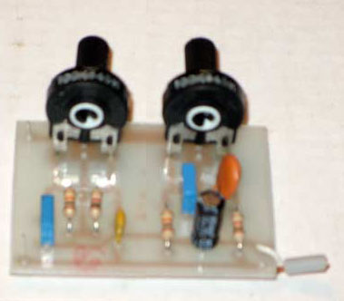
Bass and treble circuits can be combined to form a two control tone adjust circuit, as shown here.

PARTS LIST
R110kΩ
R21kΩ
R310kΩ
VR1100kΩ
VR2100kΩ
C10.01µF
C20.1µF
C30.001µF
C40.01µF
C54.7µF 16V
C64.7µF 16V

VR1 for Bass Control

VR2 for Treble Control

Bass and Treble controls of about ±10 dB boost or cut. It should be useful in a wide variety of situations.


Please send your ideas, which are very important for our success…

Electronic Circuits Control CircuitsPreAmplifier Circuits

Post navigation

Previous post
Next post

Comments (8)

  1. seetharaman says:
    April 29, 2010 at 3:38 pm

    Hi add ahigh impedance buffer in the input and an amplifier with 20dB gain after the tone control to take care of attenuation in the tone control circuit

    Reply
  2. sohel says:
    May 15, 2010 at 11:59 am

    How get satellite dish circuit diagram? Plz mail me……

    Reply
  3. iqbal says:
    December 27, 2010 at 7:55 pm

    hi sir, i need information using bc548 npn transistor on bass controling circuts.

    Reply
  4. alex says:
    August 6, 2014 at 7:33 pm

    Why is the electrolytic capacitor positioned like that, i mean isin’t it supposed to be the other way around?

    Reply
    1. Caloy says:
      June 10, 2015 at 10:50 pm

      Hi!
      I’m just a newbie here…
      But I think its not an issue if it’s reversed… 🙂

      I didn’t put the 2 electrolytic caps as shown…
      Coz, I put it in the middle of my amp. & pre-amp. that had the same value of caps…

      Reply
  5. vishal says:
    November 4, 2014 at 3:49 pm

    How to connect input or songs in mobile to the given bass treble circuit?

    Reply
  6. marcelo says:
    November 12, 2014 at 10:11 am

    what capacitor that produce more tweet

    Reply
    1. Vimal says:
      January 19, 2015 at 12:26 pm

      Pico capacitors 103/ 2A103J or 0.001uf

      Reply

Leave a Reply Cancel reply

Your email address will not be published. Required fields are marked *

  • Diagrams
  • Privacy Policy
  • Software
  • Contact

Recent Posts

  • LM317 CONSTANT CURRENT CALCULATOR
  • 5V buck converter – LM2576 simple DIY project
  • ICL7107 PANEL METER
  • Precision 1Hz clock generator circuit
  • Toggle to Momentary Switch Using 555 Monostable

Categories

  • Circuit Tutorials
  • Electronic Circuits
  • Electronic Software

AC Projects Alarm Circuits Amplifier Circuits Amplifiers Antenna Circuits Battery Charger Calculator software Circuit Designer Control Circuits Converter circuits Crossover Circuits Data Sheets Digital Circuits Electronic Switch Flasher Circuits Game Circuits IC Programmer IC Programming Indicator Circuits LED Circuits Light Circuits Logic Circuits Measuring Circuits Meter Circuits Microchip Motor Circuits Music Circuits Oscillator Circuits PCB Designer PIC Power Amplifier Power Guard Power Supply PreAmplifier Circuits Radio Circuits Regulator Circuits Regulator Diagrams Regulator Schematics RF Schematics Sensor Circuits Tester Circuits Timer Circuits Transmitter Circuits Tutorials Vacuum Tube

©2025 Electronic Circuits | WordPress Theme by SuperbThemes