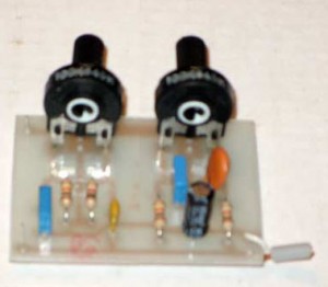
Bass Treble Tone Control Circuit
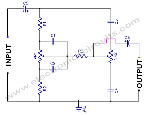
Bass and treble circuits can be combined to form a two control tone adjust circuit, as shown here.

| PARTS LIST | |
| R1 | 10kΩ |
| R2 | 1kΩ |
| R3 | 10kΩ |
| VR1 | 100kΩ |
| VR2 | 100kΩ |
| C1 | 0.01µF |
| C2 | 0.1µF |
| C3 | 0.001µF |
| C4 | 0.01µF |
| C5 | 4.7µF 16V |
| C6 | 4.7µF 16V |
VR1 for Bass Control
VR2 for Treble Control
Bass and Treble controls of about ±10 dB boost or cut. It should be useful in a wide variety of situations.
Please send your ideas, which are very important for our success…
Hi add ahigh impedance buffer in the input and an amplifier with 20dB gain after the tone control to take care of attenuation in the tone control circuit
How get satellite dish circuit diagram? Plz mail me……
hi sir, i need information using bc548 npn transistor on bass controling circuts.
Why is the electrolytic capacitor positioned like that, i mean isin’t it supposed to be the other way around?
Hi!
I’m just a newbie here…
But I think its not an issue if it’s reversed… 🙂
I didn’t put the 2 electrolytic caps as shown…
Coz, I put it in the middle of my amp. & pre-amp. that had the same value of caps…
How to connect input or songs in mobile to the given bass treble circuit?
what capacitor that produce more tweet
Pico capacitors 103/ 2A103J or 0.001uf