Skip to content
Electronic Circuits

DIY Hobby projects, diagram, schematic

Electronic Circuits

DIY Hobby projects, diagram, schematic

Filament Light Dimmer Circuit

electronicecircuits, April 28, 2010August 17, 2023
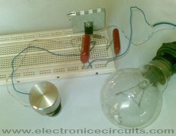
filament light dimmer using bt136 triac DB3 diac

Filament Light Dimmer Circuit

This simple triac dimmer can be used to control incandescent filament lamps up to 200W. The circuit operates on the phase-control principle.
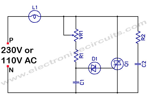
filament light dimmer circuit using bt136 triac DB3 diac
PARTS LIST
R110kΩ 0.5W
R2100Ω 0.5W
VR1500kΩ Potentiometer
C1330n (0.33µF)
C2100n (0.1µF)
D1DB3 Diac
Q1BT136 Triac
L1Filament Light

The main control is provided by VR1. This determines the rate at which C1 charges and hence the point along the mains waveform at which the voltage on C2 reaches the breakdown voltage  of the diac (D1), which is when the triac is triggered.
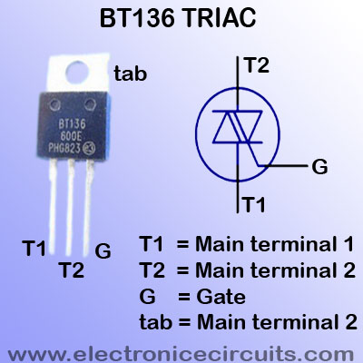
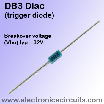
BT136 triac pin configuration Passivated, sensitive gate triacDB3 Diac trigger diode
BT136 Triac pin configurationDB3 Diac

Interference suppression is provided by R2 and C2.

This light dimmer is directly connected to mains. So be careful.

The potentiometer should have a plastic spindle.

Please send your ideas, which are very important for our success…

Electronic Circuits AC ProjectsControl Circuits

Post navigation

Previous post
Next post

Comments (15)

  1. CNA Certification says:
    June 6, 2010 at 1:56 pm

    Great site. A lot of useful information here. I’m sending it to some friends!

    Reply
  2. Autism Symptoms says:
    June 7, 2010 at 1:30 pm

    Pretty nice post. I just stumbled upon your blog and wanted to say that I have really enjoyed browsing your blog posts. In any case I’ll be subscribing to your feed and I hope you write again soon!

    Reply
  3. roclafamilia says:
    October 21, 2010 at 6:21 pm

    Helpful blog, bookmarked the website with hopes to read more!

    Reply
  4. Andrew P. says:
    February 18, 2012 at 1:33 am

    The cheapest commercial light dimmers omit C2 and R2. The best interference-suppressed triac dimmers add a choke — 20 to 30 turns of heavy Formvar insulated solid copper wire wound on a ferrite slug — in series with the dimmer. The purpose of the choke is to slow down the fast switching edges and reduce radio frequency interference (RFI) that can wipe out radio reception on the AM band for radios in the same room or adjacent rooms. At 2011 prices, the cheapest dimmers can be purchased for $6 to $10. The better interference-suppressed dimmers can cost $25 to $30. Choosing a triac with slower switching characteristics will greatly reduce radio frequency generation at the expense of requiring a larger heat sink.

    Reply
  5. kilo says:
    February 28, 2012 at 4:58 am

    thanx

    Reply
  6. Robert says:
    July 20, 2012 at 1:06 pm

    Is Dimmable CFL (Compact FLuorescent Lamp) Ballast applicable for this circuit instead of incandescent filament lamps?

    Reply
  7. Deebwebs says:
    November 8, 2012 at 5:30 pm

    Hi,
    Great site with awesome projects, thanks and keep going.

    I’ve got a question, can we use this circuit to control the speed of a motor, like simple drilling machine (about 750 W)?

    Thanks again..

    Reply
  8. abhi says:
    January 1, 2013 at 12:07 pm

    Awesome…thnx

    Reply
  9. Lsener says:
    February 11, 2013 at 5:58 pm

    very good project

    Reply
  10. OHMark says:
    August 11, 2013 at 11:27 am

    Please help me. Is it ok if i replace the filament light to LED light? And what type of capacitor did you use in the circuit? Thanks. 🙂

    Reply
  11. skytipsbd says:
    August 28, 2013 at 2:07 pm

    Thank you very much. Please need an idea when i go to the shop they don’t know diac or triac, just give me another named. which is known the shopper?

    Reply
  12. ghorbani says:
    October 19, 2014 at 5:04 pm

    nice post , thank you

    Reply
  13. enhassan says:
    November 6, 2014 at 9:02 am

    very good

    Reply
  14. Malihe says:
    November 14, 2014 at 2:56 am

    Thank you very much

    Reply
  15. sergio says:
    March 1, 2015 at 3:44 am

    esta bueno todo pero no anda este proyectoooo, esta mal puesta la carga

    Reply

Leave a Reply Cancel reply

Your email address will not be published. Required fields are marked *

  • Diagrams
  • Privacy Policy
  • Software
  • Contact

Recent Posts

  • LM317 CONSTANT CURRENT CALCULATOR
  • 5V buck converter – LM2576 simple DIY project
  • ICL7107 PANEL METER
  • Precision 1Hz clock generator circuit
  • Toggle to Momentary Switch Using 555 Monostable

Categories

  • Circuit Tutorials
  • Electronic Circuits
  • Electronic Software

AC Projects Alarm Circuits Amplifier Circuits Amplifiers Antenna Circuits Battery Charger Calculator software Circuit Designer Control Circuits Converter circuits Crossover Circuits Data Sheets Digital Circuits Electronic Switch Flasher Circuits Game Circuits IC Programmer IC Programming Indicator Circuits LED Circuits Light Circuits Logic Circuits Measuring Circuits Meter Circuits Microchip Motor Circuits Music Circuits Oscillator Circuits PCB Designer PIC Power Amplifier Power Guard Power Supply PreAmplifier Circuits Radio Circuits Regulator Circuits Regulator Diagrams Regulator Schematics RF Schematics Sensor Circuits Tester Circuits Timer Circuits Transmitter Circuits Tutorials Vacuum Tube

©2025 Electronic Circuits | WordPress Theme by SuperbThemes