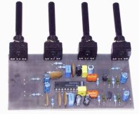
LM1036 Stereo Tone ( Bass, Treble, Volume, Loudness, Balance ) Controller Circuit
The LM1036 is a DC controlled tone (bass/treble), volume and balance circuit for stereo applications in car radio, TV and audio systems.
This stereo tone controller circuit uses mono controller to controlling tone.
Features
- Wide supply voltage range, 9V to 16V
- Large volume control range, 75 dB typical
- Tone control, ±15 dB typical
- Channel separation, 75 dB typical
- Low distortion, 0.06% typical for an input level of 0.3Vrms
- High signal to noise, 80 dB typical for an input level of0.3 Vrms
- Few external components required

NOTE:
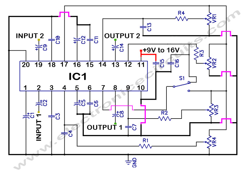
- VR1 = BASS CONTROLLER
- VR2 = VOLUME CONTROLLER
- VR3 = BALANCE CONTROLLER
- VR4 = TREBLE CONTROLLER
- S1 = LOUDNESS SWITCH
| PARTS LIST | |
| R1 | 47kΩ |
| R2 | 47kΩ |
| R3 | 47kΩ |
| R4 | 47kΩ |
| VR1 | 47kΩ |
| VR2 | 47kΩ |
| VR3 | 47kΩ |
| VR4 | 47kΩ |
| C1 | 47µF 25V |
| C2 | 0.47µF |
| C3 | 0.01µF (103) |
| C4 | 0.22µF (224) |
| C5 | 10µF 25V |
| C6 | 0.39µF (394) |
| C7 | 0.22µF (224) |
| C8 | 10µF 25V |
| C9 | 0.47µF |
| C10 | 0.01µF (103) |
| C11 | 0.39µF (394) |
| C12 | 10µF 25V |
| C13 | 0.22µF (224) |
| C14 | 10µF 25V |
| C15 | 10n (103) |
| C16 | 0.22µF (224) |
| IC1 | LM1036N |
| S1 | Switch |
Four control inputs provide control of the bass, treble, balance and volume functions through application of DC voltages from a remote control system or, alternatively, from four potentiometers which may be biased from a zener regulated supply provided on the circuit.

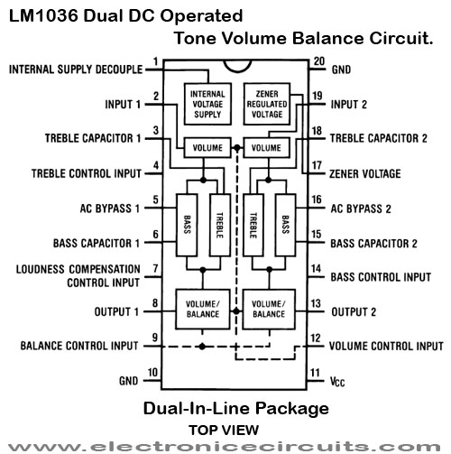
Each tone response is defined by a single capacitor chosen to give the desired characteristic. By changing the values of capacitor connected to tone controlling unit, you can control bass and treble levels. pin 3 and pin 18 of IC are for treble and pin 6 and pin 15 for bass.

Please send your ideas, which are very important for our success…
Is there a PCB layout available for this circuit?
can you please sujjest an audio processor that can be controlled by micro controller?
this circuit fault because boom sound