Skip to content
Electronic Circuits

DIY Hobby projects, diagram, schematic

Electronic Circuits

DIY Hobby projects, diagram, schematic

4011 Touch Control Switch Circuit

electronicecircuits, June 3, 2010August 17, 2023
4011 Touch Control Switch Circuit designing electronicecircuits.com

4011 Touch Control Switch Circuit

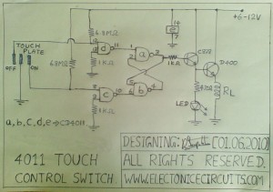
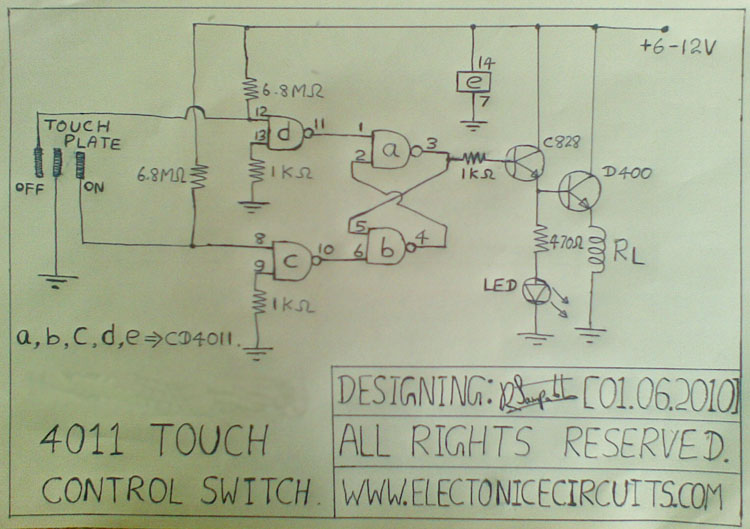
This touch control switch circuit designs by using two NAND gates and RS Flip-Flop.
4011 Touch Control Switch

4011 Touch Control Switch Circuit diagram

4011 Touch Control Switch Circuit designing electronicecircuits.com

you can increase or decrease sensitivity by increase or decrease 6.8MΩ resistor values.
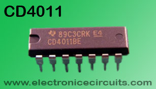
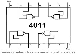
cd4011 Quad 2 Input NAND gate IC top view4011 Quad 2-Input NAND gate IC top view
4011 QUAD 2-INPUT NAND GATE

All four positive-logic NAND gates may be used independently.

On any one gate, with either or both inputs low, the output will be high; with both inputs high, the output will be low.

more images,

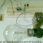
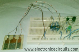
4011 Touch Control Switch with relay and 230v light4011 Touch Control Switch on light4011 Touch Control Switch

Please send your ideas, which are very important for our success…
Electronic Circuits Electronic SwitchSensor Circuits

Post navigation

Previous post
Next post

Comments (4)

  1. student grants says:
    June 4, 2010 at 7:54 am

    this post is very usefull thx!

    Reply
  2. best cookbooks says:
    October 12, 2010 at 8:27 am

    After reading this I thought it was very informative. I appreciate you taking the time and effort to put this post together. Once again I find myself spending way to much time both reading and commenting. But so what, it was still worth it!

    Reply
  3. zaklady bukmacherskie says:
    October 27, 2010 at 5:58 pm

    You post informative articles, i have bookmarked for future referrence !

    Reply
  4. john says:
    April 8, 2015 at 4:45 am

    I love etectronic so i went to lean more.thanks for post

    Reply

Leave a Reply Cancel reply

Your email address will not be published. Required fields are marked *

  • Diagrams
  • Privacy Policy
  • Software
  • Contact

Recent Posts

  • LM317 CONSTANT CURRENT CALCULATOR
  • 5V buck converter – LM2576 simple DIY project
  • ICL7107 PANEL METER
  • Precision 1Hz clock generator circuit
  • Toggle to Momentary Switch Using 555 Monostable

Categories

  • Circuit Tutorials
  • Electronic Circuits
  • Electronic Software

AC Projects Alarm Circuits Amplifier Circuits Amplifiers Antenna Circuits Battery Charger Calculator software Circuit Designer Control Circuits Converter circuits Crossover Circuits Data Sheets Digital Circuits Electronic Switch Flasher Circuits Game Circuits IC Programmer IC Programming Indicator Circuits LED Circuits Light Circuits Logic Circuits Measuring Circuits Meter Circuits Microchip Motor Circuits Music Circuits Oscillator Circuits PCB Designer PIC Power Amplifier Power Guard Power Supply PreAmplifier Circuits Radio Circuits Regulator Circuits Regulator Diagrams Regulator Schematics RF Schematics Sensor Circuits Tester Circuits Timer Circuits Transmitter Circuits Tutorials Vacuum Tube

©2025 Electronic Circuits | WordPress Theme by SuperbThemes