
555 Variable Frequency Square Wave Generator
This simple 555 Variable Frequency Square Wave Generator produces a variable frequency output of 2800Hz to 120KHz with this values.

| PARTS LIST | |
| R1 | 2.2kΩ |
| R2 | 4.7kΩ |
| VR1 | 250kΩ |
| C1 | 0.001µF (102) mylar capacitor |
| C2 | 0.01µF (103) mylar capacitor |
| IC1 | NE555 |
The 555 is connected for astable operation. Here the timing resistor is now split two sections, R1 and R2+VR1, with the discharge pin 7 connected to the junction of R1 and R2+VR1. When the power supply connected, the timing capacitor C1 charge towards 2/3 Vcc through R1 and R2+VR1. When the capacitor voltage reaches 2/3 Vcc, the upper comparator triggers the flip-flop and the capacitor start to discharge towards ground R2+VR1. When the discharge reaches 1/3 Vcc, the lower comparator is triggered and a new cycle is started.
The capacitor is then periodically charged and discharged between 2/3 Vcc and 1/3 Vcc respectively. The output state is High during the charging cycle for a time period t1, so that
t1=0.693(R1+R2+VR1)C1
The output state is low during the discharge cycle for a time period t2, given by
t2=0.693(R2+VR1)C1
Thus, the total period charge and discharge is
T=t1+t2
=0.693[R1+2(R2+VR1)]C1 (seconds)
so that the output frequency is given as
f=1/T
=1.443/{[R1+2(R2+VR1)]C1} (You can get frequency in KHz, when R1, R2, VR1 in KΩ and C in µF)
Example:
R1=2.2KΩ
R2+VR1=100KΩ
C1=0.001µF
F=1.443/{[2.2+2(100)]×0.001}
=7.136 KHz
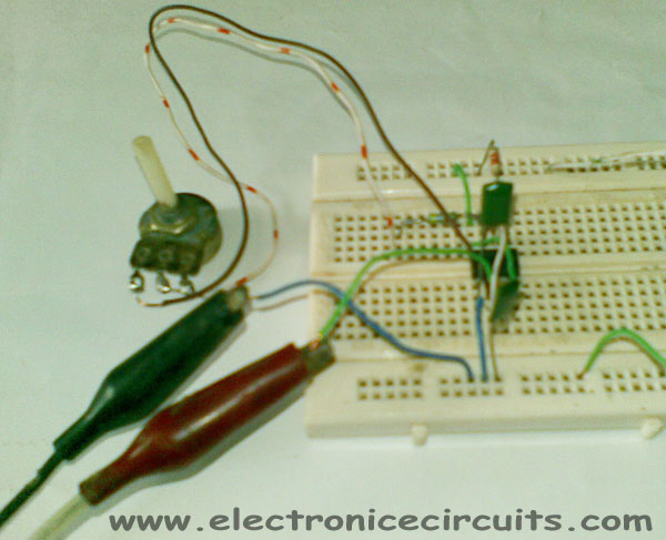
Frequency is adjusted with potentiometer VR1.
To get accurate frequency, you can use regulated power supply.
Please send your ideas, which are very important for our success…
well written blog. Im glad that I could find more info on this. thanks
Very nice post, this is just the information I needed. TYVM
I am gonna make this nice little circuit…
very very good site
Ótimo.
Muito bom mesmo.
Poderia colocar mais outros modelos para hobistas.
I need to generate a frequency from 10HZ to 200HZ using 555.Please help me in selecting the values R1,R2 and C1.
Hey!
First of all, great post, thanks for that.
I am currently waiting for the parts for this circuit to arrive and in the meanwhile I have simulated it with NI Multisim. My problem is that i get a very unstable (if that’s what that is called?) frequency.
Kinda like this: http://img132.imageshack.us/img132/9382/7kr5.png
I hope anyone can help me out.
Okay I already solved the problem, silly me chose the wrong power supply.
Thanks for the post though
Now I built the circuit and attached a small speaker to it and all that happens is that the voltage goes up once. I have attached a 9V battery to test it and double-checked all the items used. Could you help me out here?
Hi thanks a lot for the post. I’m looking to make a similar circuit but with output varying from t=0.25s to t=0.05s. Please help me know the required resistor and capacitor values for this.
Thank You
Do you have any video of that? I’d care to find out some additional information.
Hiii
This is nice post ..Thank you for this information