Skip to content
Electronic Circuits

DIY Hobby projects, diagram, schematic

Electronic Circuits

DIY Hobby projects, diagram, schematic

AC Neon Lamp filament or Semiconductor blown fuse Indicator

electronicecircuits, July 3, 2014August 21, 2023
AC Neon Lamp filament or Semiconductor blown fuse Indicator circuit

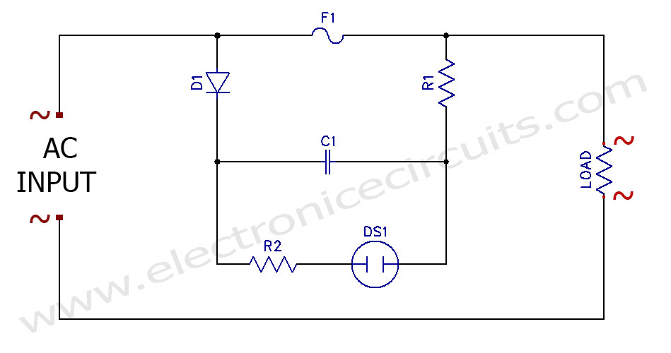
AC Neon lamp filament or semiconductor blown fuse indicator circuit

This simple circuit tells you have a blown fuse without removing the fuse from its holder or semiconductor fuse status. This neon lamp fuse indicator circuit makes neon lamp flash up if a fuse blows or open.

The fault finding point of view  there is a disadvantage of the semiconductor type fuses. It is they haven’t filaments to indicate fuse state. because we need a this type fuse indicator.

AC Neon Lamp filament Semiconductor blown fuse Indicator light circuit
PARTS LIST
R1560kΩ
R2100kΩ
C10.1µF 400V
D11N4001
DS1NEON LAMP
F1FUSE

As lone as the fuse is good, the fuse is conductive, so there is no voltage appear between the fuse connection. However if the fuse is open or blown the full supply voltage appears between fuse connections. At this time the neon lamp will start to flash on and off.

C1, R1, R2 and neon lamp act as very low frequency neon oscillator. neon flash rate can be altered by changing the value of C1, R1 and R2.

This blown fuse indicator will work with a wide range of AC supply voltages from 90V to 300V. The neon flash rate also depends on the supply voltage. So you need to change C1, R1 and R2 valves to get desired flash rate.

Above circuit can be used with few milliampere to many ampere fuse.

AC Neon Lamp blown fuse Indicatorblown fuse Indicator lightfuse failure state circuit

Please send your ideas, which are very important for our success…

Electronic Circuits Flasher CircuitsIndicator Circuits

Post navigation

Previous post
Next post

Comments (6)

  1. H.Perera says:
    July 4, 2014 at 10:46 am

    Very useful. Thank you very much

    Reply
  2. mk says:
    July 4, 2014 at 5:00 pm

    very nice lllmeess u
    long time

    Reply
  3. Jan Durand says:
    July 7, 2014 at 1:31 pm

    Unfortunately D1 is placed directly across the AC supply with nothing limiting the current., hence it will fail spectacularly with all the flames and smoke it can muster.
    Please fix this!

    Reply
    1. admin says:
      July 7, 2014 at 9:00 pm

      I fixed my circuit diagram. Thanks!

      Reply
  4. Nova Eletronica says:
    July 13, 2014 at 8:23 am

    Interestingly, the cool !!! Bi Volt! it works from 90V to 300V.. Nice!.
    Thank

    Reply
  5. JOJO says:
    March 23, 2015 at 12:55 pm

    good job

    Reply

Leave a Reply Cancel reply

Your email address will not be published. Required fields are marked *

  • Diagrams
  • Privacy Policy
  • Software
  • Contact

Recent Posts

  • LM317 CONSTANT CURRENT CALCULATOR
  • 5V buck converter – LM2576 simple DIY project
  • ICL7107 PANEL METER
  • Precision 1Hz clock generator circuit
  • Toggle to Momentary Switch Using 555 Monostable

Categories

  • Circuit Tutorials
  • Electronic Circuits
  • Electronic Software

AC Projects Alarm Circuits Amplifier Circuits Amplifiers Antenna Circuits Battery Charger Calculator software Circuit Designer Control Circuits Converter circuits Crossover Circuits Data Sheets Digital Circuits Electronic Switch Flasher Circuits Game Circuits IC Programmer IC Programming Indicator Circuits LED Circuits Light Circuits Logic Circuits Measuring Circuits Meter Circuits Microchip Motor Circuits Music Circuits Oscillator Circuits PCB Designer PIC Power Amplifier Power Guard Power Supply PreAmplifier Circuits Radio Circuits Regulator Circuits Regulator Diagrams Regulator Schematics RF Schematics Sensor Circuits Tester Circuits Timer Circuits Transmitter Circuits Tutorials Vacuum Tube

©2025 Electronic Circuits | WordPress Theme by SuperbThemes