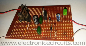
7805 5V 1 Amp Regulated Power Supply with Overvoltage Protection Circuit
This is the 7805 5 volts 1 ampere Regulator with Overvoltage Protection Circuit. Most of the COMS, microcontrollers and TTL ICs require a well regulated power supply. these ICs can easily damage when supply voltage is increased. basically this circuit provides overvoltage protection but it has over current, reverse polarity, and the regulator IC protection. So you don’t need to worry about power supply.
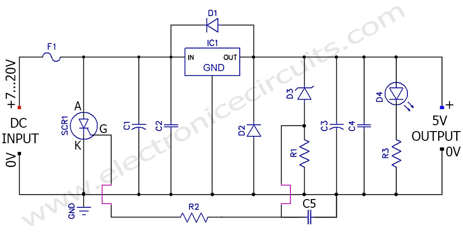
| PARTS LIST | |
| R1 | 330Ω ¼W |
| R2 | 33Ω ¼W |
| R3 | 220Ω ¼W |
| C1 | 100µF 50V |
| C2 | 0.1µF |
| C3 | 10µF 16V |
| C4 | 0.01µF |
| C5 | 0.1µF |
| D1 | 1N4001 |
| D2 | 1N4001 |
| D3 | 6.2V Zener Diode ¼W |
| D4 | LED |
| IC1 | 7805 regulator IC |
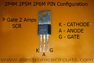
| SCR1 | 2P4M OR Similar 2A SCR |
| F1 | 1A FUSE |
Our circuit design using 5V regulator IC, SCR and ZENER diode. Actually this is a crowbar circuit. It is an electrical circuit used to prevent an overvoltage condition of a power supply unit from damaging the circuits attached to the power supply. If the voltage regulator (7805) is faulty, the supply voltage could be applied to the load and it will damage our sensitive circuits. So we need this type of protection circuit.
When the output voltage exceeds 6.2V, Zener diode conducts. That voltage will switch on SCR, so this provides a short circuit to ground and fuse will be blown. The C1 capacitor is present to ensure that short spikes to not trigger the SCR. Also you can change the protection level by varying the values of D3 and R1. The D1 provides reverse bias protection and D2 provides output polarity reversal protection to the regulator IC.
If you get more than 400mA current, please use this regulator IC with suitable heat sink.
 |
 |
 |
|
Please send your ideas, which are very important for our success…
nice thing
I give thanks to you for the posts you send to me
Very good design .Thank u for post.
good ideaer but how to now V of ZD 6.2V
whats is mark ?
Thanks
how if add indicator full and auto cut off?
its a nice circuit, i use it to charge my phone but it was very slow. Please how can i increase the current? Pls i need help.
what is max output current and voltage of your circuit..??
what if we apply exactly 9v battery???
I am iranian .very to enjoy of site you .successful
Very good design .Thank u for post.can you send new high Ampere power supply circuit diagram