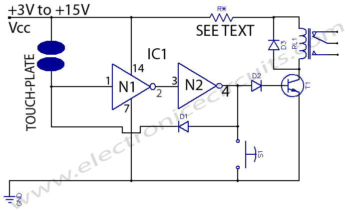
CD4069 touch switch circuit
Here is a touch switch that can be used to drive LEDs, relays etc through a buffer transistor stage. It may be built around any CMOS inverter chip. but preferably, around 4069 IC. The 4069 can be run off any regulated DC supply from +3V up to +15V.

| PARTS LIST | |
| R* | 100Ω (For 9V) |
| D1 | IN4148 |
| D2 | IN4148 |
| D3 | IN4148 |
| T1 | BC148 |
| IC1 | 4069 |
| S1 | Push Button Switch |
| RL1 | RELAY |
When there is no connection between the pair of touch contacts wired in the circuit, the input of N1 is low and thus its output is high, which makes the input of N2 high and output low. thus no current flows through D1 and D2 in this condition.
When the contacts are bridged by a finger, N1’s input becomes high and it’s output becomes low: making the output of N2 high. Diode D1 now conducts and feeds a return pulse to the input of N1, thus effectively latching the circuit in the ‘on’ state. The output of N2 is fed through a buffer transistor state and switches on a relay, LED etc.
As 4069 (or 7404) IC has six such stages in it, three switches of this type can be made from each. Resistor R is used just to lessen the load on the battery and the transistor. For 9V power supply, vaule of R should be about 100 ohms. Values of R for other supply voltages (Vcc) can be derived form the relationship
R=( 1000 * Vcc )/Im
where Im is the relay’s current rating in mA. Since about of 100mA should be drawn from the power supply, a 100mA relay of appropriate voltage (say, 12V) may be selected for use.
Please send your ideas, which are very important for our success…