Skip to content
Electronic Circuits

DIY Hobby projects, diagram, schematic

Electronic Circuits

DIY Hobby projects, diagram, schematic

2 LED CMOS Flasher Circuit Diagram

electronicecircuits, January 14, 2011August 15, 2023
2 Two LED CMOS Flasher Circuit

Two LED CMOS Flasher Circuit Diagram

This is a simple 2 led cmos robot ( flasher, multivibrator ) circuit using CD4069 six inverter IC.

2 two LED CMOS Flasher multivibrator Circuit Diagram

PARTS LIST
R13.3MΩ
R2470Ω
C10.1µF (104)
D1, D2LED
IC1CD4069

Circuit Description

cd4069 six inverter cmos ic
CD4069 six inverter CMOS IC

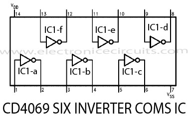
Inverters IC1-a and IC1-b from a multivibrator and IC1-c is a buffer. Inverter IC1-d is connected so that its output is opposite that of IC1-c; when  pin 6 is high, then pin 8 is low and vice versa. Because pins 6 and 8 are constantly changing state, first one LED and then the other is on since they are connected in reverse. The light seems to jump back and forth between the LED’s.

The R2 resistor limits LED current. Depending upon the supply voltage used, the value of the resistor may have to be changed to obtain maximum light output. To change the switching rate, change the value of capacitor.

Two LED robot multivibrator circuitTwo LED Flasher Circuit Diagram

Please send your ideas, which are very important for our success…

Electronic Circuits Flasher CircuitsLED Circuits

Post navigation

Previous post
Next post

Comment

  1. mokhlis says:
    January 20, 2011 at 8:04 pm

    thank for all the time to give me more detalse

    Reply

Leave a Reply Cancel reply

Your email address will not be published. Required fields are marked *

  • Diagrams
  • Privacy Policy
  • Software
  • Contact

Recent Posts

  • LM317 CONSTANT CURRENT CALCULATOR
  • 5V buck converter – LM2576 simple DIY project
  • ICL7107 PANEL METER
  • Precision 1Hz clock generator circuit
  • Toggle to Momentary Switch Using 555 Monostable

Categories

  • Circuit Tutorials
  • Electronic Circuits
  • Electronic Software

AC Projects Alarm Circuits Amplifier Circuits Amplifiers Antenna Circuits Battery Charger Calculator software Circuit Designer Control Circuits Converter circuits Crossover Circuits Data Sheets Digital Circuits Electronic Switch Flasher Circuits Game Circuits IC Programmer IC Programming Indicator Circuits LED Circuits Light Circuits Logic Circuits Measuring Circuits Meter Circuits Microchip Motor Circuits Music Circuits Oscillator Circuits PCB Designer PIC Power Amplifier Power Guard Power Supply PreAmplifier Circuits Radio Circuits Regulator Circuits Regulator Diagrams Regulator Schematics RF Schematics Sensor Circuits Tester Circuits Timer Circuits Transmitter Circuits Tutorials Vacuum Tube

©2025 Electronic Circuits | WordPress Theme by SuperbThemes