Skip to content
Electronic Circuits

DIY Hobby projects, diagram, schematic

Electronic Circuits

DIY Hobby projects, diagram, schematic

3V Battery Powered Stereo Amplifier Circuit TDA2822M

electronicecircuits, June 30, 2015August 11, 2023
7805 5V 1A Regulated Power Supply with Overvoltage Protection Circuit

DIY simple low voltage dual power amplifier circuit TDA2822M

This is a simple low voltage stereo power amplifier circuit using single 8 pins IC. You can easily operate it using two battery cell. TDA2822M IC work within 1.8V to 15V. This can use for many applications like small battery powered radio, alarm, portable cassette player, headphone amplifier and more.
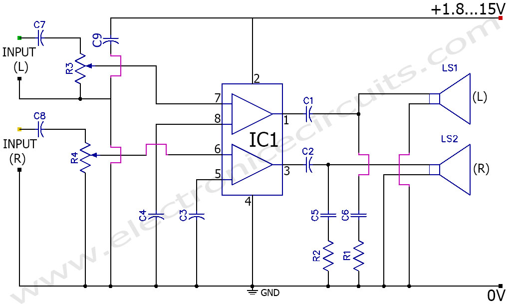
3V Battery Powered Stereo  Amplifier Circuit TDA2822M

PARTS LIST
R14.7Ω 1/4W
R24.7Ω 1/4W
R3, R410kΩ stereo potentiometer
C1470µF 16V
C2470µF 16V
 C3100µF 16V
C4100µF 16V
C50.1µF
C60.1µF
C71µF 16V
C81µF 16V
C9100µF 25V
IC1TDA2822M
LS11W 4Ωspeaker
LS21W 4Ω speaker

TDA2822M is a monolithic integrated circuit in 8 lead Minidip package.

TDA2822M 3v stereo amplifier pin configuration

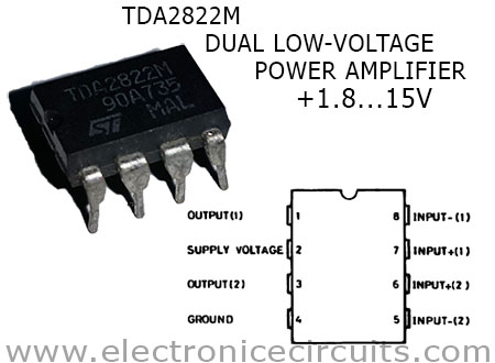
TDA2822M has Low crossover distortion, Supply voltage down to 1.8V, Low quiescent current and Bridge or Stereo configuration. This IC can deliver a maximum power of 1000 milli-watts per channel, for a total of 2 watts.

Speaker Output Power (each channel)
(f = 1kHz, d = 10%)
4Ω 3V110mW
4Ω 4.5V320mW
4Ω 6V650mW
8Ω 6V380mW
8Ω 9V1000mw (1W)

R1, C6 and R2, C5 are resistor capacitor branch. They are connect between speaker out and ground to preventing oscillation and improving high frequency stability. C9 capacitor use for power supply filter.

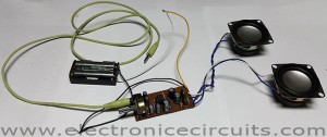
This stereo power amplifier is very simple. because you can easily assemble it using vero board. Also TDA2822M amplifier can made very small and low cost. Additionally I use 3.5mm audio port for connecting portable device.

3V Battery Powered Stereo Amplifier Circuit TDA2822M Video

Battery Powered Amplifier TDA2822MDIY 3V Stereo Headphone AmplifierTDA2822M dual low voltage audio amplifier

Please send your ideas, which are very important for our success…

Electronic Circuits AmplifiersPower Amplifier

Post navigation

Previous post
Next post

Comments (7)

  1. Pingback: DIY simple low voltage dual power amplifier circuit TDA2822M | Electronic Circuits
  2. m.yasir says:
    July 1, 2015 at 9:31 am

    Circuit seems quite simple and useful

    Reply
  3. Cassiano Hernandez Conzatti says:
    July 1, 2015 at 11:08 am

    Thank you very much, it is precisely what I was looking for. Because, besides being an electronics engineer, I am a musician too, and I use to make recordings with my piano and accordion. Greetings to all members of this community.

    Reply
  4. Eng. Sherif Bekhit says:
    July 1, 2015 at 11:47 am

    Hi dear
    Very good pwer amp. very low parts circuit

    Reply
  5. m says:
    July 2, 2015 at 2:02 pm

    Goods today
    Imees your more time
    Dot forget

    Reply
  6. m says:
    July 2, 2015 at 2:02 pm

    Thank

    Reply
  7. mahesh says:
    July 4, 2015 at 1:22 pm

    Circuit seems quite simple and useful

    Reply

Leave a Reply Cancel reply

Your email address will not be published. Required fields are marked *

  • Diagrams
  • Privacy Policy
  • Software
  • Contact

Recent Posts

  • LM317 CONSTANT CURRENT CALCULATOR
  • 5V buck converter – LM2576 simple DIY project
  • ICL7107 PANEL METER
  • Precision 1Hz clock generator circuit
  • Toggle to Momentary Switch Using 555 Monostable

Categories

  • Circuit Tutorials
  • Electronic Circuits
  • Electronic Software

AC Projects Alarm Circuits Amplifier Circuits Amplifiers Antenna Circuits Battery Charger Calculator software Circuit Designer Control Circuits Converter circuits Crossover Circuits Data Sheets Digital Circuits Electronic Switch Flasher Circuits Game Circuits IC Programmer IC Programming Indicator Circuits LED Circuits Light Circuits Logic Circuits Measuring Circuits Meter Circuits Microchip Motor Circuits Music Circuits Oscillator Circuits PCB Designer PIC Power Amplifier Power Guard Power Supply PreAmplifier Circuits Radio Circuits Regulator Circuits Regulator Diagrams Regulator Schematics RF Schematics Sensor Circuits Tester Circuits Timer Circuits Transmitter Circuits Tutorials Vacuum Tube

©2025 Electronic Circuits | WordPress Theme by SuperbThemes