50 Hz 60 Hz frequency generator circuit using crystal oscillator
You can generate 50Hz or 60Hz using this frequency generator. This oscillator can be used as the front end of circuits that require precision pulses.
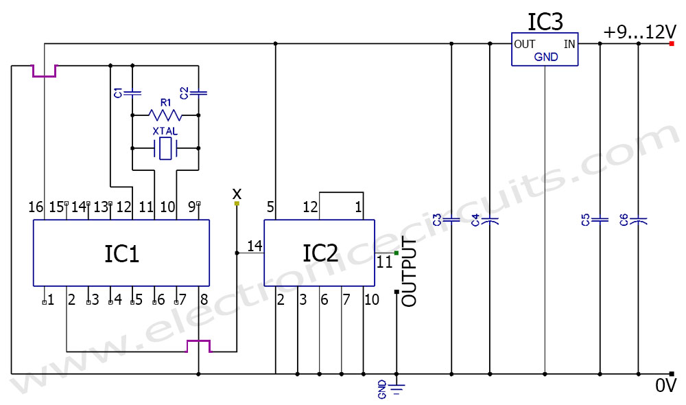
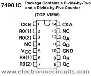
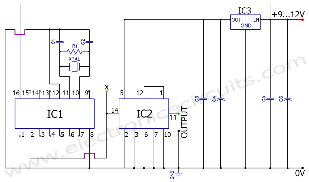
A crystal is used in the circuit to generate clock pulses. The circuit uses two counter ICs CD4060 and 7490 to divide the basic frequency to generate 50Hz or 60Hz pulses.
| PARTS LIST | |
| R1 | 2.2MΩ |
| C1 | 24pF |
| C2 | 24pF |
| C3 | 0.01µF |
| C4 | 47µF 16V |
| C5 | 0.1µF |
| C6 | 100µF 16V |
| XTAL | 4.096MHz or 4.9152MHz Crystal |
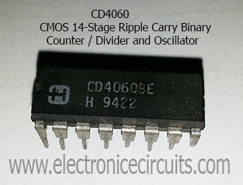
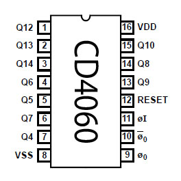
| IC1 | CD4060 |
| IC2 | 7490 (SN74LS90N) |
| IC3 | 7805 Regulator |
| “X” is a test point. | |
CD4060 act as an oscillator and frequency divider here this is arranged to divide by 8192Hz which gives 600hz when you using 4.9152MHz crystal or 500hz when you using 4.096MHz crystal. That frequency further divided by 10 using 7490 IC is to obtain 50Hz or 60Hz output.
4.096MHz Crystal
4.096MHz=4096Khz=4096000Hz
4096000/8192=500Hz
500/10=50Hz
4.9152MHz Crystal
4.9152MHz=4915.2KHz=4915200Hz
4915200/8192=600Hz
600/10=60Hz
 |  |
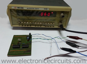
You can check CD4060 crystal oscillator and frequency divider work correctly via “X” test point. when you use 4.096MHz crystal “X” point gives 500Mhz output and 4.9152MHz crystal gives 600Hz output. If you don’t need a test point you can ignore it.
 |  |
This frequency generator circuit gives 50Hz as output when the crystal is 4.096MHz. Crystal must be 4.9152MHz if you need 60Hz.
 |  |  |  |  |
UPDATE: (09/08/2018)
Please use below circuit, If circuit fail to oscillate.
UPDATE 50hz 60hz frequency signal generator circuit diagram using crystal oscillator
Please send your ideas, which are very important for our success…
You have the voltage regulator IC3 input and output designators on the schematic marked backwards. The input is the sourcing power supply, the output is the 5v regulated output.
That is my mistake. I correct it. Thanks!
Im very glad to sending agin
which pin of ic2 is used for the output?
It is number 11 pin of IC2. Thanks!
Hey, thanks. what is the amplitude of the output waveform for this circuit?
Hi, i am building a circuit similair to this one and was wondering if you/someone could list me the type of capacitors used in the circuit, labeling them C1, C2, C3 and so on.
i seem to keep blowing mine up. PLEASE HELP!!
Great job
if i want to design like this circuit but my load drains 17A at 110Vdc. can you give the modification which i have to do?
I really appreciate your help
Thanks for all
Hi,
Can I adjust the frequency up or down by about 10 to 15 percent with the addition of a trimpot / trimmer capacitor somewhere? I need 50 Hz and 67.5 Hz
Many thanks