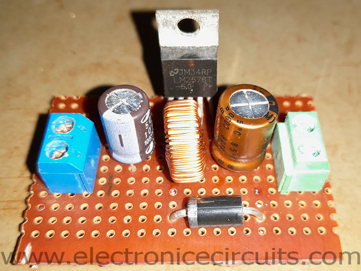
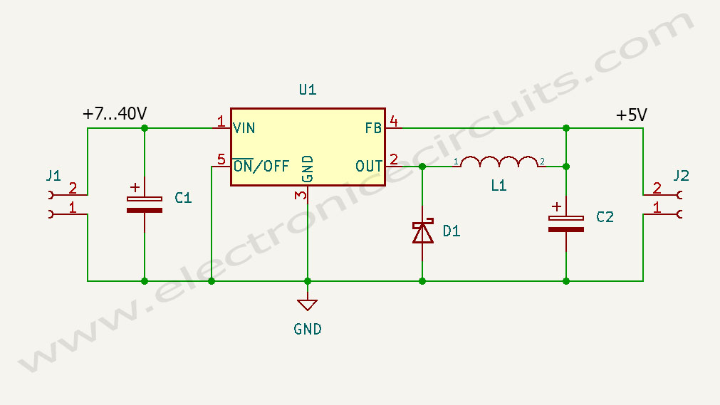
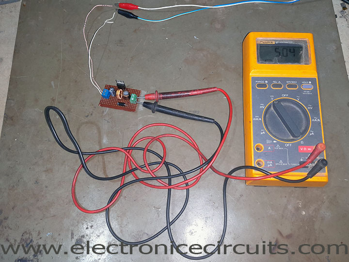
This is a simple DIY 5V 3A voltage regulator circuit using LM2576 buck converter IC. So that can use as 5V car charger(12V to 5V), 5V regulated power supply and many more five volts power requirements. Below circuit uses very few components. Because anyone can make it using basic electronic knowledge.
The LM2576 series offers a high-efficiency replacement for popular three-terminal linear regulators. Because it substantially reduces the size of the heat sink, and in some cases no heat sink is required.
| PARTS LIST | |
| C1 | 100µF 50V |
| C2 | 1000µF 10V |
| D1 | 1N5822 |
| L1 | 100µH |
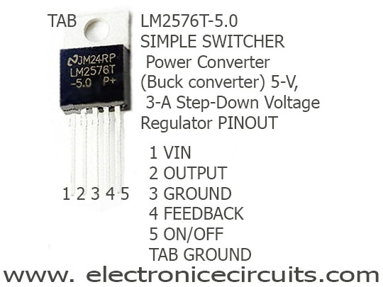
| U1 | LM2576T-5.0 |
The LM2576 series of regulators are monolithic integrated circuits that provide all the active functions for a step-down (buck) switching regulator, capable of driving 3-A load with excellent line and load regulation. These devices are available in fixed output voltages of 3.3 V, 5 V, 12 V, 15 V, and an adjustable output version. Above circuit uses 5V version.
LM2576 PINOUT
INPUT capacitor (C1) To maintain stability, it should be at least a 100-μF electrolytic capacitor. Also the capacitor leads to be short, and place near the regulator.
The inductor (L1) chosen must be rated for operation at the LM2576 switching frequency (52 kHz) and for a current rating of 1.15 × ILOAD.
OUTPUT capacitor (C2) should be low ESR type. Because low ESR types for low output ripple voltage and good stability. The voltage rating of the capacitor must be at least 1.5 times greater than the output voltage. For a 5V regulator, a rating of at least 8 V is appropriate, and recommends a 10V to 25V rating. In general, low value or low voltage (less than 12 V) electrolytic capacitors usually have higher ESR numbers. Higher voltage electrolytic capacitors generally have lower ESR numbers, and for this reason it can be necessary to select a capacitor rated for a higher voltage than can normally be needed. Because ESR Below 0.20Ω value recommends. But reducing the ESR below 0.03 Ω can cause instability in the regulator.
Catch Diode (D1), fast-recovery diode with soft recovery characteristics is a better choice. Standard 60-Hz diodes (for example, 1N4001 or 1N5400, and so on) are also not suitable. So Schottky diodes provide the best efficiency, especially in low output voltage switching regulators. Because we use 1N5822 Schottky diode for above 5V buck converter circuit.
Also you can go through this 7805 5V 1A Regulated Power Supply with Overvoltage Protection Circuit
Please send your ideas, those are very important for our success…