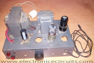
Single Ended Class A 6V6 6J5 Valve (Vacuum Tube) Amplifier Circuit
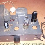
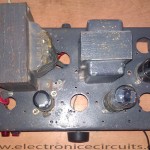
This is my first successful vacuum tube (valve) project. The output of this small amplifier in which a 6V6GT output pentode is connected as triode is about 4.5 watts.
This project involves a single ended audio amplifier. It has resistive input network, a driver stage, and an output stage to a typical 8 ohm loudspeaker load. Also use minimum of supportive passive components for biasing and coupling duties. Power-supply voltage is provided by full wave diode rectification of 230 VAC by a magnetic transformer. Because this design provides a quality audio amplifier.
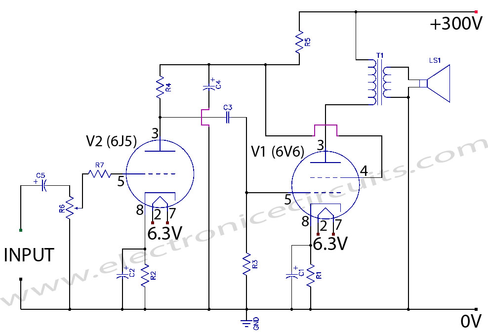
Valve amplifier circuit diagram
| PARTS LIST | |
| R1 | 470Ω 1W |
| R2 | 4.7KΩ 1W |
| R3 | 1MΩ ¼W |
| R4 | 100KΩ 2W |
| R5 | 15KΩ 2W |
| R6 | 10KΩ Volume Control |
| R7 | 1kΩ ¼W |
| C1 | 33µF 250V |
| C2 | 33µF 250V |
| C3 | 0.1µF 400V |
| C4 | 10µF 250V |
| C5 | 1µF 100V |
| V1 | 6V6GT Tube |
| V2 | 6J5GT Tube |
| T1 | Audio Output Transformer, Primary 5KΩ; Secondary 8Ω |
| LS1 | 10W 8Ω Speaker |
The major factor involving the design of this single ended output stage is matching an available output tube to an available output transformer (OT) , which can provide the proper impedance matching. Using typical operating parameters, the 6V6 power tube, operating in triode mode, has an ideal load impedance of 5k Ohm, and generates about 4.5 watts of power. Also an OT was used, handling 8 watts and providing impedance matching from a 5k primary to an 8 ohm secondary (common loudspeaker impedance).
Tube amplifier power supply

| PARTS LIST | |
| R1 | 100KΩ 3W |
| C1 | 0.047µF 400V |
| C2 | 0.047µF 400V |
| C3 | 0.22µF 1000V |
| C4 | 220µF 450V |
| D1-D4 | 1N4007 |
| F1 | 500mA Fuse |
| S1 | Switch |
| DS1 | Neon Lamp |
| T1 | Mains Transformer, Secondaries 230V, 150mA; 6.3V 3.5A |
The amplifier uses a simple linear power supply to develop 300VDC. Heater voltages are supply directly from the 6.3VAC taps on the secondary of the power transformer. Also other secondary windings, rated at 230VAC are use for the DC supply. It consists of a 4 rectifiers, variety of smoothing capacitors and resistor.
Tube Datasheets
Several construction issues were consider in the building of this amplifier. High power supply voltages, large and leaky inductive components, and high temperatures are among these considerations. Because I use old tube amplifier chassis.
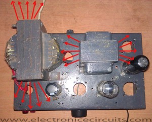
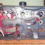
Magnetic flux expelled from the transformers as shown by the red arrows above. By placing the output transformer (OT) and power transformer (PT) at opposite ends of the chassis, and rotating their axes 90° from one another, induction noise from PT to OT reduce. Although this configuration sees flux from the OT direct at the 6V6, as a result OT flux interference reduce to the sensitive preamp stage. Also Beneath the chassis hum reduction is further achieved by winding all pairs of wire containing AC (filament heater wires, PT primary, and secondary wiring to the diode rectifier).
6V6 Tube amplifier Video
Due to the 300V power supply voltages, components carefully chosen to withstand peak conditions.
Connect valve amplifier ground and power supply ground to the chassis ground point.
Don’t touch any component when the tube amplifier connected to the power, because it used high voltage.
Please send your ideas, which are very important for our success…
Hi
R6 has to be mirrored, attaching R7 to the central terminal and C5 to the upper terminal otherwise the input impedance decreases as you decrease the volume shorting the input source at 0 volume (very bad).
Also I would increase the input resistor (again R6) to 50K LOG pot.
Cheers
Enrico
Thank you very much! I corrected my circuit diagram. But i still used 10K pot.
thank for help me
ineen more pleas
Hi !
What about R1 in power supply ???
Zdeno
Nice blogs i like it
R1 in the power supply is,or should be
a “bleeder”,used to empty the big caps
of their charge when not in use,high voltage
remains and can be dangerous!
The good value must be around 100KOhm
the 100Ohm one should stand 900watt !Nice
show on first and single start…
This is my spelling mistake. R1=100KΩ. I correct it. Thanks!
thank you for shareing!
Hi, I am based in the UK, the power voltage is 240 volts. Could someone please tell me how to modify the power supply circuit so it could take 240 volts and step it up to 300 volts, Thank you.
c5 must be after pot, before r7,
non polarized.
the best value is 0.1uF.
after r7 must be grid resistor.
the best value is 470k.
c2 may be 100uF, best choice is tantalum.
c3 may be larger, up to 0.47uF or 2x 0.22.
c4 may be larger, 100 – 220uF.
6v6 must have g2 (pin 4) resistor
1 – 2.2K, then go to supply.
output transpormer primary may be
paralellized with 220pF 1500v.
power supply must have stand by switch,
after the first capacitor, because first
must warm up tubes, about 30 sec.
power supply may be combined with rectifier tube +
2 pieces of silicon diodes for slower high voltage
applying to tubes. best choice is may be 5y3gt.
there is example on the internet.
for the output tube, choice is very good.
best sounding tube, after the 2a3.
C5 is fine just where it is! R5 and R7 puts the grid at 0-volt potential. Placing C5 after the R5 pot would isolate the grid from ground and screw up the bias potential between the cathode and grid. In reality the cathode current flowing through R2 makes the cathode slightly positive. This is an OLD TRICK that makes the grid appear to be Negative with respect to the Cathode. If it were this way the tube would ‘super’ conduct and burn up. Vacuum tube require REVERSE bias as opposed to transistors which require FORWARD bias.
This is very common& basic single end power amp. If to improve the quality of sound that to be selected good components to replace it. As Output Transformer’ Tube; and capacitors.
Ótimo post.