Skip to content
Electronic Circuits

DIY Hobby projects, diagram, schematic

Electronic Circuits

DIY Hobby projects, diagram, schematic

BI-Colour LED Running Lights

electronicecircuits, November 15, 2009August 19, 2023
Bi Color LED running lights disco lights night rider

BI-Colour LED Running Light Circuit

Five bi-colour LEDs are used in this circuit. These LEDs first light-up from top bottom ingreen colour one by one and then these LEDs light-up from bottom to top in red colour.
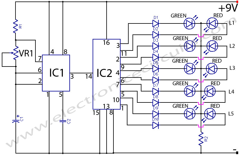
Bi-colour led running lights desco night rider 4017 circuit

PARTS LIST
R110kΩ
R2680Ω
VR1100kΩ
C122µF 16V
C20.01µF
D1-D101N4001 × 10
L1-L5Bi Colour LEDs
IC1NE555
IC2CD4017

As IC1 provides clock pulses to the input of decade counter IC2, at each clock pulse, IC2 counts from 0 to 9.

The first five pulses reach the green anodes of the bi-colour LEDs and they light in green colour.  The next five pulses reach the red anodes of the LEDs so they light-up in red colour.
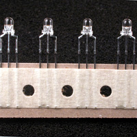
BI Colour LEDs
BI Colour LEDs

This process is continued regularly. The glowing rate of LEDs can be controlled with the help of potentiometer (VR1).

Please send your ideas, those are very important for our success…

Electronic Circuits LED Circuits

Post navigation

Previous post
Next post

Comments (9)

  1. forex robot says:
    December 17, 2009 at 11:46 pm

    Keep posting stuff like this i really like it.

    Reply
  2. PERIYASAMY says:
    December 18, 2009 at 3:17 pm

    AS I AM SUCESSFULLY FINISHED WAS YOUR CIRCUITS

    Reply
  3. seetharaman says:
    May 1, 2010 at 11:32 pm

    Hi D1 to D10 serves no pupose can be deleted. otherwise the cicuit is novel. If you have included with diodes for both LEDs to get supply at certain steps it would have become amber also.

    Reply
  4. Andrea says:
    August 6, 2010 at 2:01 am

    Thank you so much for posting all of the excellent information! Looking forward to seeintg more posts.

    Reply
  5. Sarah says:
    August 19, 2010 at 11:01 pm

    Informative blog, bookmarked the blog for hopes to see more information!

    Reply
  6. Yoram says:
    November 3, 2011 at 12:55 am

    what is the purpose of the regular diodes d1-d10 ?

    Reply
  7. disco light says:
    April 17, 2013 at 2:45 pm

    disco light

    Reply
  8. michaelabot says:
    September 16, 2014 at 2:01 am

    Q1. What if i connected 5 decade counters IC2 to pin3 of IC1 and each decade counters has the exact same circuit which has 10 diodes and 5 bi-colour LEDs?
    Q2. What if i connected 5 bi-colour LEDs in parallel to diodes : D1 – D10?

    Which one will work?

    Reply
  9. stine achonwa says:
    May 6, 2015 at 5:33 am

    thanks for accepting me.

    Reply

Leave a Reply Cancel reply

Your email address will not be published. Required fields are marked *

  • Diagrams
  • Privacy Policy
  • Software
  • Contact

Recent Posts

  • LM317 CONSTANT CURRENT CALCULATOR
  • 5V buck converter – LM2576 simple DIY project
  • ICL7107 PANEL METER
  • Precision 1Hz clock generator circuit
  • Toggle to Momentary Switch Using 555 Monostable

Categories

  • Circuit Tutorials
  • Electronic Circuits
  • Electronic Software

AC Projects Alarm Circuits Amplifier Circuits Amplifiers Antenna Circuits Battery Charger Calculator software Circuit Designer Control Circuits Converter circuits Crossover Circuits Data Sheets Digital Circuits Electronic Switch Flasher Circuits Game Circuits IC Programmer IC Programming Indicator Circuits LED Circuits Light Circuits Logic Circuits Measuring Circuits Meter Circuits Microchip Motor Circuits Music Circuits Oscillator Circuits PCB Designer PIC Power Amplifier Power Guard Power Supply PreAmplifier Circuits Radio Circuits Regulator Circuits Regulator Diagrams Regulator Schematics RF Schematics Sensor Circuits Tester Circuits Timer Circuits Transmitter Circuits Tutorials Vacuum Tube

©2025 Electronic Circuits | WordPress Theme by SuperbThemes