Skip to content
Electronic Circuits

DIY Hobby projects, diagram, schematic

Electronic Circuits

DIY Hobby projects, diagram, schematic

Crossover Network

electronicecircuits, October 4, 2009August 19, 2023
crossover network

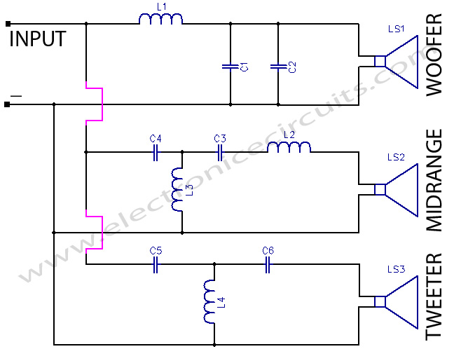
3 Way Crossover Network Circuit

Loudspeaker is a very important component of a hi-fi system.By adding a crossover network to the system of speakers, the low, high and mid-range frequencies can be separated and fed into a woofer, tweeter and mid-range speaker respectively.

3 way crossover network circuit diagram
Fig. 1 Wiring diagram for three-way crossover network
PARTS LIST
C13.3 µf  50v N.P.
C24.7 µf 50v N.P.
C33.3 µf 50v N.P.
C43.3 µf 50v N.P.
C50.68 µf
C61 µf 50v N.P.
R13.3 Ω 2W
R24.7 Ω 2W
R36.8 Ω 2W

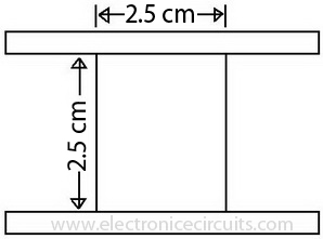
The given circuit uses four inductances of 0.1, 0.2, 0.3 and 1 mH, each having 70, 100, 120 and 200 turns of 18SWG wire on the johnson-john adhesive tape bobbins having 2.5 cm length and 2.5 cm dia.The speakers used have an impedance of 8-ohm each, and the circuit can be used for amplifiers with output rating of a maximum of 50 watts RMS per channel.

Fig. 2 air core
Fig. 2 air core

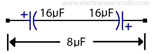
The capacitors used are non-polarised type, which can be made by connecting end to end two capacitors of double the required value, as shown. All the capacitors are 50V type.The crossover frequencies are 500 Hz and 2.5 kHz. All the inductors are air core type. Resistors are 2W type.

Fig.3 the making of a non-polarised capacitor, using two electrolytic (polarised) capacitor of twice the desired value.

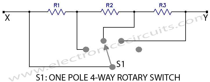
Since a high frequency producing tweeter generally sounds very loud compared to the mellower outputs of a woofer and a mid-range speaker, the tweeter’s output can be reduced by introducing the attenuation circuit shown in Fig. 4. Using one-pole, four-way switch S1, the tweeter’s output can be reduced to a desired extent or allowed to pass on unattenuated to the speaker.

Fig. 4: Tweeter attenuator

Care should be taken to connect the tweeter and the woofer in opposite phase.

Please send your ideas, those are very important for our success…


Electronic Circuits Crossover CircuitsPower Amplifier

Post navigation

Previous post
Next post

Comments (9)

  1. Large Plastic Storage Boxes says:
    March 25, 2010 at 9:11 am

    I found your blog on google and read a few of your other posts. I just added you to my Google News Reader. Keep up the good work Look forward to reading more from you in the future.

    Reply
  2. Dunk Sb Shoes says:
    June 2, 2010 at 11:55 am

    Good! What a wonderful posting! Some advice:If you ever then add pictures, it might be easiler for you to adhere to!

    Reply
  3. seotons says:
    November 10, 2010 at 7:43 pm

    Excellent brief and this article helped me alot. Say thank you I looking for your information….

    Reply
  4. soft darts says:
    December 19, 2010 at 9:23 pm

    I found your blog on google. I think it’s pretty cool.

    Reply
  5. sauron says:
    February 23, 2011 at 4:11 pm

    Its cool..
    btw, what should I do if I want to connect the croosover to my car speaker with 4ohm and 300w max..

    Reply
  6. toko elektronik says:
    November 11, 2011 at 8:34 am

    Nice xover for experiment. Thank’s

    Reply
  7. ermsk8er says:
    November 18, 2012 at 4:48 pm

    thanks for sharing your design.. may i know the value of L1, L2, L3 & L4 inductors? sorry im newbie. Thanks again!

    Reply
  8. malik says:
    September 17, 2014 at 8:35 pm

    yar resistance kdr lgy ga

    Reply
  9. angelous says:
    February 14, 2015 at 8:07 pm

    i have already try this circuit only tweeter worked the subwoofer and midrange did not work.

    Reply

Leave a Reply Cancel reply

Your email address will not be published. Required fields are marked *

  • Diagrams
  • Privacy Policy
  • Software
  • Contact

Recent Posts

  • LM317 CONSTANT CURRENT CALCULATOR
  • 5V buck converter – LM2576 simple DIY project
  • ICL7107 PANEL METER
  • Precision 1Hz clock generator circuit
  • Toggle to Momentary Switch Using 555 Monostable

Categories

  • Circuit Tutorials
  • Electronic Circuits
  • Electronic Software

AC Projects Alarm Circuits Amplifier Circuits Amplifiers Antenna Circuits Battery Charger Calculator software Circuit Designer Control Circuits Converter circuits Crossover Circuits Data Sheets Digital Circuits Electronic Switch Flasher Circuits Game Circuits IC Programmer IC Programming Indicator Circuits LED Circuits Light Circuits Logic Circuits Measuring Circuits Meter Circuits Microchip Motor Circuits Music Circuits Oscillator Circuits PCB Designer PIC Power Amplifier Power Guard Power Supply PreAmplifier Circuits Radio Circuits Regulator Circuits Regulator Diagrams Regulator Schematics RF Schematics Sensor Circuits Tester Circuits Timer Circuits Transmitter Circuits Tutorials Vacuum Tube

©2025 Electronic Circuits | WordPress Theme by SuperbThemes