Bi-direction Control Circuit For DC Motor
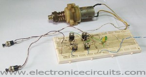
This circuit can control direction of a DC motor. In many applications we need to operate the motor in both directions Clockwise and Anticlockwise (forward and back). One way of achieving this is to connect the motor into a Transistor H-bridge circuit arrangement. H bridge is an electronic circuit that enables a voltage to be applied across a load in either direction. These circuits are often used in robotics and other applications to allow DC motors to run forwards and backwards (Bi-directional).

| PARTS LIST | |
| R1, R2, R3, R4 | 220Ω |
| R5, R6, R7 | 1KΩ |
| D1, D2, D3, D4 | 1N4001 |
| D5, D6 | LED |
| Q1, Q2 | 2SD313 |
| Q3, Q4 | 2SB507 |
| PB1, PB2 | PUSH BUTTON SWITCH (PUSH TO ON) |
| M1 | 12V DC MOTOR |
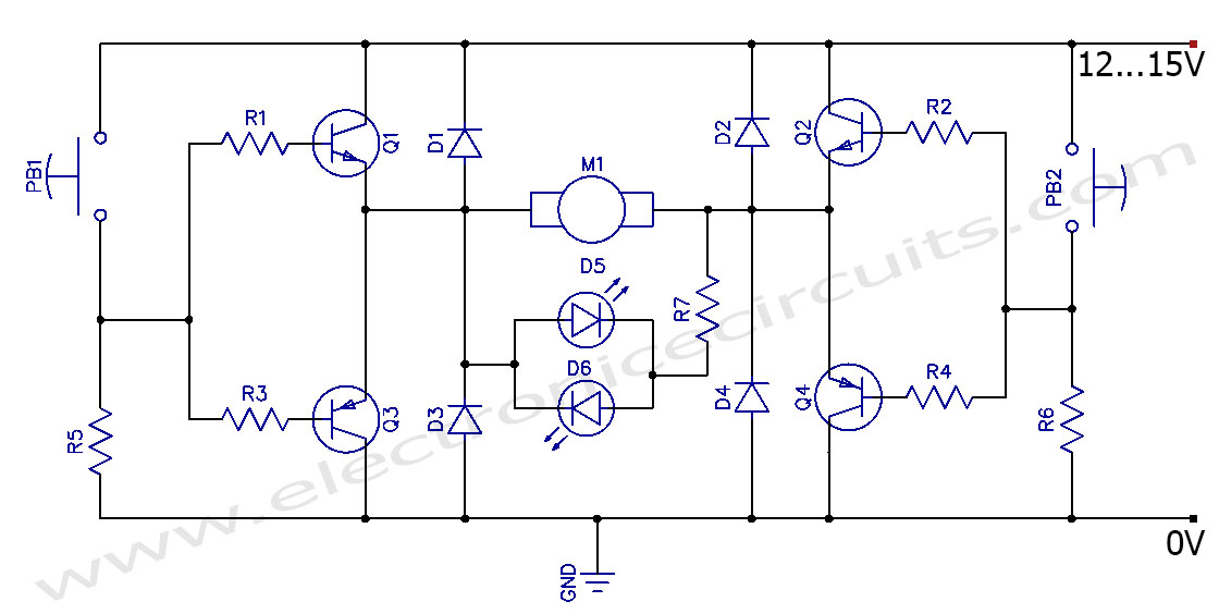
In this circuit normally PB1 and PB2 are open. So the bases of the transistors are grounded. Hence Q3 andQ4 are ON, Q1 and Q2 are OFF. The voltages at both the motor terminals is the same and hence the motor is OFF. Similarly when both PB1 and PB2 are “PUSH” the motor is OFF.
When PB1 is PUSH, Q1 becomes ON since it is NPN. This type transistor needs high potential at the base to turn ON. But the Q3 is OFF. Because it is PNP and it needs to low voltage to turn on. PB2 is still OPEN so transistor Q2 OFF and Q4 ON because low potential appear at the base of the transistors. So current flow through Q1, M1 to Q4. So motor rotates one direction.
When PB2 is ON and PB1 OFF similarly Q2 and Q3 are ON and Q1 and Q4 are OFF. Now current flows through Q3, M1 and Q2. Now motor rotates another direction.
The diodes protect the transistors. They allow back E.M.F. to bypass the transistor.
The LEDs indicate the direction of the motor rotation.
The transistors are EMITTER FOLLOWERS and the voltage on the motor will be less than the voltages of the circuit above because the output voltage will be determined by the slight drop across the 1KΩ+220Ω and the voltage drop across the base-emitter junction of the transistor. The total voltage drop to the motor (due to both sides of the bridge) will be about 2v.
When the both inputs high or low this emitter follower H-bridge circuit has not any current flow. It is the advantage of this circuit.
Please send your ideas, which are very important for our success…


Look good, I want to try for power window or electric mirros, yhanks
.!
very nice
very good .
very nice
very good.
Sorry, but what is the maximum current supports for DC motor?
how to use this circuit for 24 volts
thank you for this circuit….. its very simple and easy to understand ….. helped me in completing my project 😀 🙂
important circuit to me. Thank you
How would this work for a 18v or 24v dc motor?
Thanks
hello friend,
plz help….
i use tip42 and tip41 for replace of 2sd313 and 2sb507.
but my circuit have problem the both tip42 is too much hot when motor is working condition on forward and reverse.
sorry for my English.
good job