Skip to content
Electronic Circuits

DIY Hobby projects, diagram, schematic

Electronic Circuits

DIY Hobby projects, diagram, schematic

Electronic Coin Toss Circuit Diagram

electronicecircuits, January 31, 2011August 15, 2023
Electronic Coin Toss Circuit

Electronic Coin Toss Circuit Diagram

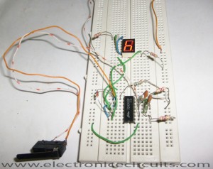
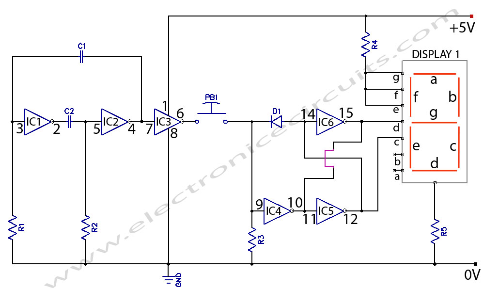
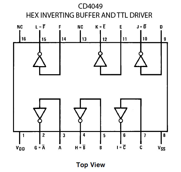
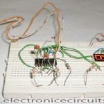
This is electronic coin toss circuit using one CD4049 IC (Hex inverting buffer and TTL driver).  This IC has six buffers and it can use independently. The buffers use as simple inverters, as voltage translators, or as current drivers for interfacing TTL or other logic.
Electronic Coin Toss Circuit Diagram
PARTS LIST
R12.7KΩ
R22.7KΩ
R315KΩ
R4220Ω
R5220Ω
C10.01µF (103)
C20.01µF (103)
D11N4148
IC1, IC2, IC3, IC4, IC5, IC6CD4049
PB1Push to on switch
DISPLAY 1common cathode 7-segment display

The gate IC1 and IC2 of the IC and resistor  – condenser network from a relaxation oscillator. Gate IC3 of the IC is a buffer which isolates the oscillator from the load. Gates IC5 and IC6 use as a flip-flop. The LEDs will glow (either head or tail) when the corresponding gate’s output is high. The output of flip-flop will change states only when the input applied are compliment logic levels, example: high and low.For this gate IC4 is used.
cd4049 hex inverting buffer and ttl driver IC

Press the switch PB1 and release it. The LED will show for chance.

You can use a 7-segment common cathode display instead of LEDs to know the chance by reading the letters h and t.

CD4049 Electronic Coin Toss CircuitElectronic Coin Toss Circuit

Please send your ideas, which are very important for our success…
Electronic Circuits Game Circuits

Post navigation

Previous post
Next post

Comments (2)

  1. free crack adobe says:
    February 3, 2011 at 9:11 pm

    i resembling it Electronic plug Toss Circuit Diagram after this im your rss reader

    Reply
  2. mamun says:
    September 18, 2014 at 2:47 pm

    nice

    Reply

Leave a Reply Cancel reply

Your email address will not be published. Required fields are marked *

  • Diagrams
  • Privacy Policy
  • Software
  • Contact

Recent Posts

  • LM317 CONSTANT CURRENT CALCULATOR
  • 5V buck converter – LM2576 simple DIY project
  • ICL7107 PANEL METER
  • Precision 1Hz clock generator circuit
  • Toggle to Momentary Switch Using 555 Monostable

Categories

  • Circuit Tutorials
  • Electronic Circuits
  • Electronic Software

AC Projects Alarm Circuits Amplifier Circuits Amplifiers Antenna Circuits Battery Charger Calculator software Circuit Designer Control Circuits Converter circuits Crossover Circuits Data Sheets Digital Circuits Electronic Switch Flasher Circuits Game Circuits IC Programmer IC Programming Indicator Circuits LED Circuits Light Circuits Logic Circuits Measuring Circuits Meter Circuits Microchip Motor Circuits Music Circuits Oscillator Circuits PCB Designer PIC Power Amplifier Power Guard Power Supply PreAmplifier Circuits Radio Circuits Regulator Circuits Regulator Diagrams Regulator Schematics RF Schematics Sensor Circuits Tester Circuits Timer Circuits Transmitter Circuits Tutorials Vacuum Tube

©2025 Electronic Circuits | WordPress Theme by SuperbThemes