LM317 Power Supply Circuit
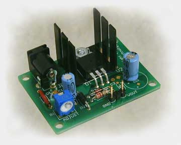
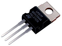
The output is adjustable between 1.25 and 13.5 Volts with a maximum current limit of 1.5 Amps. The LM317K regulator is internally protected from current and thermal overloads. A heat sink will be required for most LM317 applications however.

| PARTS LIST | |
| R1 | 220 Ω |
| R2 | 2 KΩ Variable Resistor |
| C1 | 3300 µf 50v |
| C2 | 10 µf 25v |
| C3 | 1 µf 25v |
| C4 | 0.1 µf |
| D1 | 100V 5A bridge rectifier |
| D2 | IN 4007 |
| D3 | IN 4007 |
| IC1 | LM 317 |
| T1 | 18 VAC 2AMP |
| F | 250mA |
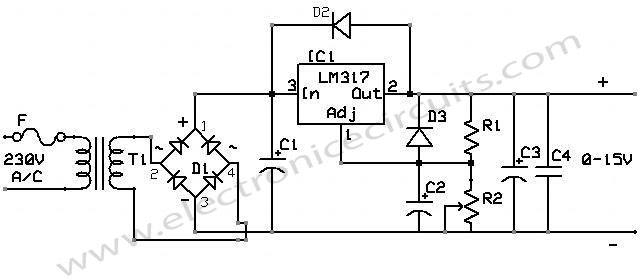
The values of R1 and R2 are not critical but R1 should not be larger than 270 ohms. For a fixed voltage output R2 should be selected to give the desired maximum output voltage for a given R1 value. See the calculation on the drawing.
The diodes D2 and D3 in the circuit prevent damage to the regulator during certain adverse conditions such as the output voltage being higher than the input voltage to the regulator or the capacitor across R2 from discharging through the adjustment terminal of the regulator. These conditions will be rare but ten cents worth of protection can save the cost of a new regulator.

An Ammeter could be added to the circuit by placing it between the filter capacitor and the input terminal of the regulator.
Also check this post for calculation – lm317 calculator
Please send your ideas, which are very important for our success.


I really liked your blog! good
Hello, i found your site at yahoo and you are providing interesting stuff. I like it,
I found this web site at yahoo and line this articles. Already bookmarked.
thanks for the information
its good but give some more information
thankyou sir i am studing forEEE engineering from tamilnadu.i need more circuit sir . so please send me emil.
basically i am intersting in this field.so i need more information sir.
I adj is between 100uA and 50uA, right?