Skip to content
Electronic Circuits

DIY Hobby projects, diagram, schematic

Electronic Circuits

DIY Hobby projects, diagram, schematic

Micro Ampere Meter

electronicecircuits, September 12, 2009August 19, 2023
micro-ampere-meter

The microampere meter circuit

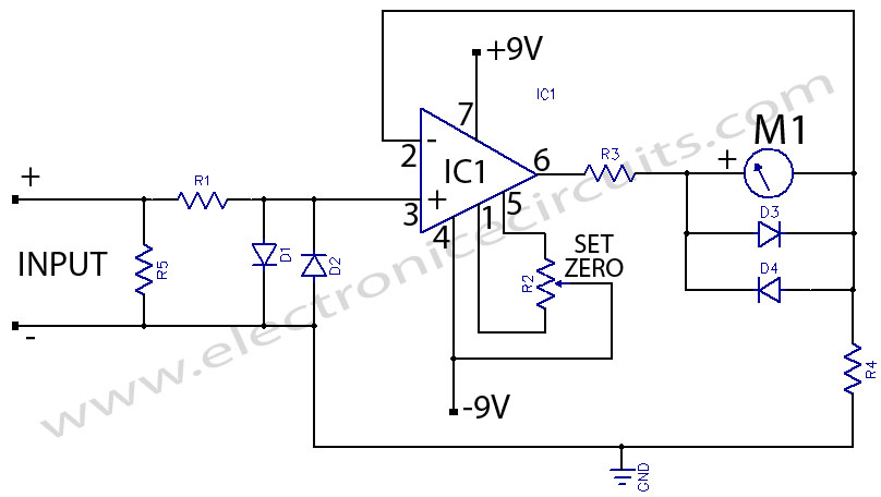
The microampere meter gives full scale deflection for 0.1 V input. The current to be measured is passed through a known resistance R and the voltage drop across it is measured.
micro ampere meter circuit diagram

PARTS LIST
R110KΩ
R210KΩ
R33.3KΩ
R4100Ω
D1IN 4001
D2IN 4001
D3IN 4001
D4IN 4001
IC1LM 741
M11 mA meter

The this table shows the relationship between different values of R5 and the current that will give full scale deflection.

R5Full Scale current
100KΩ1µA
10KΩ10µA
1KΩ100µA
100Ω1mA

A high impedance Micro Ampere meter using a 741 .The operational amplifier is used as a non-inverting dc amplifier in which the negative feedback is through a dc meter requiring 1mA for full scale deflection.

Diodes D1 and D2 protect the IC from accidental excessive input voltages and diodes D3 and D4 protect the meter from overloads.


Please send your ideas, those are very important for our success…

Electronic Circuits Indicator CircuitsMeasuring CircuitsMeter Circuits

Post navigation

Previous post
Next post

Comments (7)

  1. Large Plastic Storage Boxes says:
    March 28, 2010 at 10:34 pm

    I found your blog on google and read a few of your other posts. I just added you to my Google News Reader. Keep up the awesome work Look forward to reading more from you in the future.

    Reply
  2. Large Plastic Storage Boxes says:
    March 28, 2010 at 10:49 pm

    I really liked your blog! super

    Reply
  3. cna training says:
    May 5, 2010 at 10:31 am

    My cousin recommended this blog and she was totally right keep up the fantastic work!

    Reply
  4. pozycjonowanie stron krakow says:
    October 14, 2010 at 2:55 am

    I like your post. I’ll surely be peeping into it again soon! 🙂

    Reply
  5. pozycjonowanie stron krakow says:
    October 14, 2010 at 3:14 am

    Good to know, thanks for the usefull knowledge.I just love it!

    Reply
  6. my blog says:
    November 2, 2010 at 11:28 am

    Really informative blog post.Really thank you!

    Reply
  7. HTTP://Megafiles.co/ says:
    May 8, 2013 at 12:11 am

    Good information. Lucky me I ran across your blog by accident (stumbleupon).
    I have book marked it for later!

    Reply

Leave a Reply Cancel reply

Your email address will not be published. Required fields are marked *

  • Diagrams
  • Privacy Policy
  • Software
  • Contact

Recent Posts

  • LM317 CONSTANT CURRENT CALCULATOR
  • 5V buck converter – LM2576 simple DIY project
  • ICL7107 PANEL METER
  • Precision 1Hz clock generator circuit
  • Toggle to Momentary Switch Using 555 Monostable

Categories

  • Circuit Tutorials
  • Electronic Circuits
  • Electronic Software

AC Projects Alarm Circuits Amplifier Circuits Amplifiers Antenna Circuits Battery Charger Calculator software Circuit Designer Control Circuits Converter circuits Crossover Circuits Data Sheets Digital Circuits Electronic Switch Flasher Circuits Game Circuits IC Programmer IC Programming Indicator Circuits LED Circuits Light Circuits Logic Circuits Measuring Circuits Meter Circuits Microchip Motor Circuits Music Circuits Oscillator Circuits PCB Designer PIC Power Amplifier Power Guard Power Supply PreAmplifier Circuits Radio Circuits Regulator Circuits Regulator Diagrams Regulator Schematics RF Schematics Sensor Circuits Tester Circuits Timer Circuits Transmitter Circuits Tutorials Vacuum Tube

©2025 Electronic Circuits | WordPress Theme by SuperbThemes