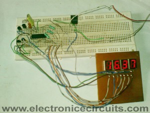
PIC16F84 12 or 24 Hour Digital Clock Circuit Diagram And Programming
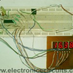
This PIC digital clock circuit is based on a 16F84 microcontroller. it uses four 7-segment displays.The software in the microcontroller allows for very accurate timekeeping.
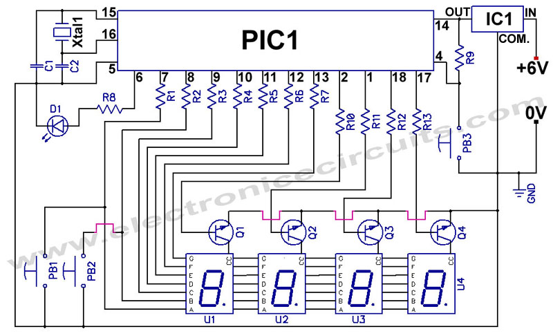
| PARTS LIST | |
| R1 – R8 | 100Ω |
| R9 | 10kΩ |
| R10 R13 | 10kΩ |
| C1 | 22pF |
| C2 | 22pF |
| D1 | LED |
| U1 – U4 | Common Cathode 7 Segment Display |
| Q1 – Q4 | C828 |
| Xtal1 | 4 MHz Crystal |
| IC1 | 7805 Regulator IC |
| PIC1 | PIC 16F84 OR PIC16F84A |
| PB1 -PB3 | Push to ON push button switch |
PB1 for set minutes.
PB2 for set hours.
PB3 for Reset.
D1 LED indicate seconds.
Notes:
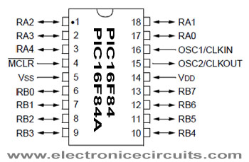
- Design this circuit diagram on veroboard or pcb using 18 pin IC base.
- Program your PIC (pic16f84 or pic16f84a) using PIC Programmer with ic-prog programmer software and this .HEX file. You can follow these instructions.
- Install PIC on IC base.
- Supply power to your circuit and set time using PB1 and PB2.
Thats all. 🙂
Also provided asm files, so you can develop or modify this clock circuit.
Download digital clock asm and hex files.
Please send your ideas, which are very important for our success…
This is such a great resource that you are providing and you give it away for free. I enjoy seeing websites that understand the value of providing a prime resource for free. I truly loved reading your post. Thanks!
seconds led indicate accurately but time is not display.why can help me
i also try this n i have same problem i think that problem in 16f84 ic programs if u find it plz reply me
thank u
Great site. A lot of useful information here. I’m sending it to some friends!
nice work, i needed just that for my project.
nice, thank you so much 😉
can you add a pcb for this?? i cant create one, it took me 3hrs but still failed..
can u send me the pcb file plx
Does somebody know how to reprogram the .asm file?
This is what I want to happen:
If clock strikes 6:00 am, 11:00 am, 16:00 pm, there will be an output that will be triggered.
We are planning to use the circuit for a feeder project. Please help. Thank you.
i have constructed this working good with battery but not with home supply, when i switched on and off the appliances in the same room the device is (time) reset whats the problem give me solution
thank you….
please post the pin configuration of c828
Hi There
I have also constructed this clock and facing same Problem ,Have you find any Solution for this Problem.Pls Reply on my Email mailjrooprai@gmail.com .Thanks in advance.
Yours
Jaspreet singh
c828 is npn or pnp transistor?
npn Transistor
can i use bc 557 or BC 547 or BC548 ??
Collector current of BC546, 547 and 548 is 100mA. For small displays it is okay to use BC547 or 548, while for larger displays it is recommended to use BC337 or 338 which their collector current is 800mA. You may also use ULN2003 or ULN2803 instead of individual transistors.
BC557 is PNP so it is not suitable in this circuit.
Thanks for this info! However, it might be a tip to put more comments in the code so the inexperienced user knows what’s going on – for instance which part of the code controls the actual clock? What do the ten or so short lines directly under the header do?
nice work i made it
hey I have a problem on how to program a 16f84 with assembly language to drive a 16-segment LED which would spell out a word. just one display which shows a letter at a time.
Please can you help?
thank you
Hi buddy, can you put an ASM or HEX CODE for an clokc of 4.8MHz I have an sueper stable master oscilator for 4.8MHz and I want to use this temp controlled osc. to manage this clock projet.
Tahnks you in advance.
Alberto
can anyone tell me how to change between 24hrs and 12hrs? do i need to change the program?
can anyone convert this hex codes for 16f628a?
i have a problem with this
first i has constructed this circuit power is given by 6v stepdown transformer with 5v voltage regulator. when i switched on the fan or tube light the clock is reset what is the problem please suggest me thank you.
Thanks, I’m going to use the code in my nixy tube clock, still waiting for my new pic micro controllers to come in from sparkfun, but so far so good, if i decide to add an alarm function to it then ill send you the new code.
hi!!!!!!!!!!!
please tell me that which ic will work better,PIC 16F84 OR PIC16F84A.
thankyou,
from kiran
Es un Magnifico trabajo y es el mejor sitio que e encontrado con informacion veridica quisiera saber si a la terminal No. 3se le puede agregar una serie de alarmas para tocar un timbre de escuelas los eventos son 07:00 07:50 08:40 09:30 10:20 10:35 10:40 11:30 12:20 13:10 13:30 14:20 15:10 16:00 16:50 17:05 17:10 18:00 18:50 19:40 y que su duracion fuera de 5seg por evento les agradesco su informacion si requieren lo pcb del circuito de reloj y de los displays con gusto se los enviare gracias
hi…………….
can u please tel me the cost price of 16F84 microcontroller in indian rupee……………….
thnks
from kiran
100Rupees
hi!!!!!!!!!!!!!!!
i dont have a rs232 cable. can i use the pin which has both sided rs232 type pin.but i can connect it to my pc.
thankyou ,
from kiran
can i ask if it is ok to change the 7 segment size, i will make it 7 segment (5inch)?
Malas noticias este reloj se ADELANDA U MINUTO POR DIA
Hello, my problem that the clock forward a few seconds per day. How I can adjust the .asm code.
Thanks
hi kiran!
as on my experience using this microcontroller in my robot arm, I do prefer the PIC16f84. I do have a problem on PIC16f84A on the porta side. I can’t figure out why it can not set a pulse.
thanks!
-deleng
hello there again Kiran!
you can use a usb to rs232 port which can be bought on any computer or comp. accessory booth that can suit on your computer…
thanks!
-deleng
when we try the program it just counts 1-9 and all of the seven segments were counting at the same time. can anyone help us with this?
HIIIIIIIIIIII can you tell me the basic ipplemention of digital circuit diagram????????
PIC16F84 12 or 24 Hour Digital Clock Circuit
hi i liked very much your project. can you please tell me if you can make it with a button to change it from clock to time counter?
Has anyone had any luck making this work? I need an alternative for the transistors.
Actually what I need one lamp will glow regularly say from 6 pm to 10 pm and another from 9pm to 6 am as per choose.
s’il vous plait comment je peut connecter 38 afficheurs 7 segment au microcontroleur 16f877(comment mettre 152 broches dans 32 entrées)
svp j’attend votre reponse pour mon projet
merci d’avance.
can u send me pcb?? really need
I need some help to make this schematic and hex to work with Common Anode display type please… i made the schmeatic with CA and not working with the actual HEX file….
I have to make a PIC based project related to the field of instrumentation and control
Can send to me the PCB layout, schematic layout, hex file and assembly file? I really interest to this project and i do this project as my final year project.
how use that?
So what is this range of use ?
Wha type of transistor are you using NPN or PNP?
Thank s fred
hoy many volts of capacitor.?
hi
this clock circuit diagram is very nice. Weal com
learn circuit
hi i think this is cool one stil im not make it but soon as posible im going to do it. in fact i have little problem, can anyone please tell me how do i change 12 and 24 hours ? there is no switch (push button) for it.
thank you for your comments…….
t.c
There are 2 hex-files, one for 24h and one for 12h. You must chose when programming the chip.
The decimal point lights on your pictures, but I can not see where it is connected on the schematics. Where is it connected and how?
Does it also works with a pic16f627,628 or 876?
hello sir
the hex file not proper working.7 Segment Display show only 8 .plz soluition this problum and resend hex file 12 hour,
plz help me. i m making a digital clock on a pic based.. i installed a program in microcontroler..bt display showing only 8 digit num, i didnt understand wat is this prob and how to solve it…
can any one submit the proteu simulation file for this project
Hi,
Is there anyone here who knows how to add zulu time as well as a timer and stop watch?
Cheers,
Manfred
Clock is so simple and works good but it’s going FAST! Transistors are ss9014 appropriate.
Request adjusting xtall,etc.
Dear Sirs,
I mad this circuit but it goes fast.(2 min. a day)
How can I solve this problem. Thanks,
Nice work really but it goes fast! For newbies asm codes are not meaningful. How can we adjust accuracy and how can add rtc? Thanks a lot..
how to check if the PIC is properly installed?
I would like to use a PIC16F628A. I haven’t been able to compile. Could you tell me what changes I should make in memory locations, or configuration.
what should i change if i used common anode. 7 seg display.
thanks
@Arne: “The decimal point lights on your pictures, but I can not see where it is connected on the schematics. Where is it connected and how?”
To make the DP work, change the schematic: break the connection between pin 6 of the PIC and R8 and instead connect R8 to 7805’s out (pin 14 of the PIC). You won’t need to change the code or anything else (I’m using the 24h one).
Can i replace PIC16F84 by PIC16F628A because i only have PIC16F628A? can you post HEX file for it. Thank you very much !
I used PIC 16F84A IC, my clock is not working.
WHY?????
did your 16F84A worked now? i have the same microcontroller.
I have made this nice digital clock.
But it goes 2minutes fast per day.
Give me solution.
what is the pin configuration of C828?
Pls hw do I get the display led is it sold in d market already coupled or am to construct it
how to select 12 or 24 hours mode?
any body can send me the pic16f84a based digital clock with c code # Baker#
Hi please send the details for big 7 segment clock (only hex file)
i got prob!can anyone help me?seconds indicating led blink accurately but not indicate time on 7 segments.
Hi, I have built your digital clock and all working fine thanks except that its gaining something like 2 minutes in about 5 days.
Is there away of correcting this in the code ASM file before creating the HEX.
If so could you possibly show me what to do please.
73s Dave
I am new to this, so i faced a problem how to connect VDD/VCC pins from PIC?
Could you explain to me, how does PB1 and PB2 works?
And at what speed should I switch displays?
that’s very interesting.
etching a pcb is also a simple work.
the way of current flow of 7 segment LED Panel is always to one direction.eg common anode or common cathode. can be controlled by changing the polarity of the out put pulse . eg 00111111 and 11000000 by inverting.
can use pnp or npn transistors to withstand the load of wach 7 segment LED panel by installing the collector of the npn transistor directly to the positive rail and getting the output from the emitter of the transistor and connecting it to the common electrode of the 7 segment led panel.
and if you try to use pnp transistors, the load supplies from the common anode must be fed to the emitter of the pnp transistor and the collector must be connected to the negative rail.
i am very much interesting to follow a frequency counter circuit to measure 50.000,000 Hz as maximum reading.let me know how the timer0 and int must be configured to use the frequency counter please.
thanks and good luck.
Bandula
Don’t worry to use a vero board to assemble the circuit diagram. use a small piece of emery paper and clean all the layers first.
use a sharp scalpel to cut the unwanted lengths and connections of the vero strips. or else use a dotted board and make each and very wiring by using good quality circuit wire.
use 0.8mm good quality solder wire.
try to use some solder flux also.
keep the copy of the wiring diagram in front of you when you do your wiring.
best of luck.
bandu
I have built the circuit and it worked perfectly. it is a wonderful thing you have done. I will even want you to be my pal for i highly appreciate this work that you have put on the net to encourage others. thank you
Circuit wearing is same but display is not on what is this problem.
Sirs,
I mad this circuit but it goes fast.(2 min. a day)
How can I solve this problem. Thanks,
How can I adjust the clock as it gains two minutes everyday?
Is it okay if I put Yl-501SR-A instead c828?
sorry i was wrong. 🙂