Skip to content
Electronic Circuits

DIY Hobby projects, diagram, schematic

Electronic Circuits

DIY Hobby projects, diagram, schematic

Power Guard

electronicecircuits, September 26, 2009September 2, 2023
Power Guard Under and Over Voltage Protector

Under and Over Voltage Protector (Power Guard)

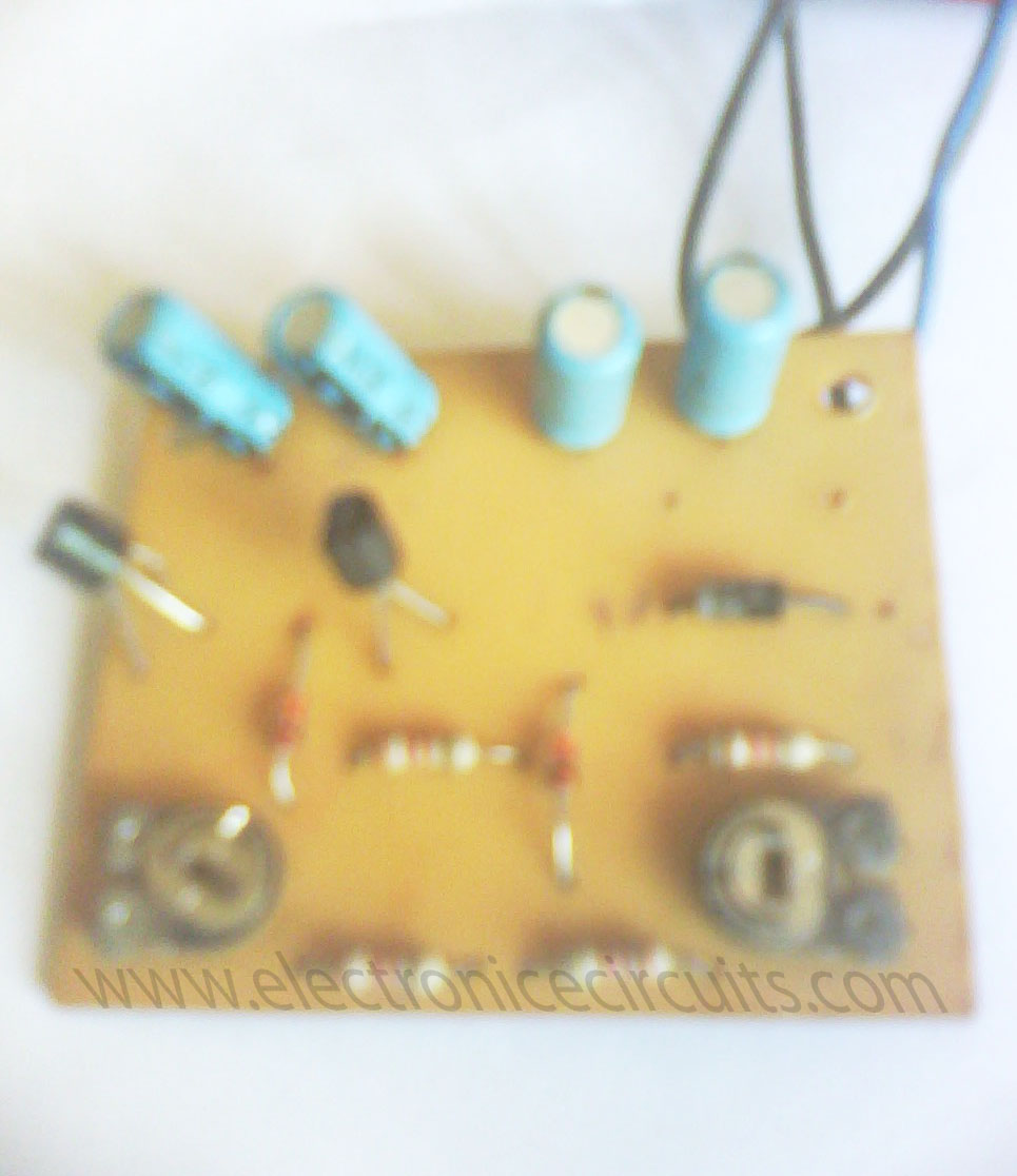
A few circuits on under/over voltage protection have appeared recently in EFY. But this power guard circuit diagram is simple, very easy to construct and inexpensive. It can be added to existing stabilisers, in which case DC power supply can be taken from the original stabiliser circuit and only a few additional components, including one relay, are required to make the circuit.
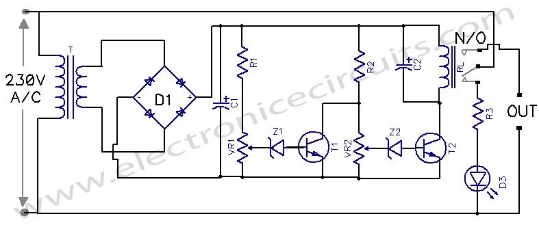
Power Guard Under and Over Voltage Protector circuit

PARTS LIST
R11KΩ
R2820Ω
R310KΩ 1/2W
C11000µF 25V
C2250µF 25V
VR14.7KΩ
VR24.7KΩ
T1HL100, SL100, BC547 or equivalent
T2HL100, SL100, BC547 or equivalent
RL12V 450Ω
Z1Bz148 or 6.8V Zener
Z2Bz148 or 6.8V Zener
D1BY126 × 4 or IN4007× 4
T12V 500mA

Above power guard circuit diagram has two preset potentiometers. When supply voltage is within limit, T2 conducting and T1 is in a non-conducting state. At low voltage, zener Z2 will not breakdown and T2 will not conduct, which results in de-energising the relay. This adjustment is done by adjusting VR2.

At high voltage, zener Z1 will breakdown and T1 will go in conducting state and the relay will de-energize. This adjustment is done by adjusting VR1. Normally-open contact of the relay is used in control circuit. Red LED gives high low voltage cut-off  indication.


Please send your ideas, those are very important for our success…

Electronic Circuits Power GuardPower Supply

Post navigation

Previous post
Next post

Comments (5)

  1. Arup Basak says:
    October 6, 2010 at 8:28 pm

    Use a good macro mode camera for taking pcb images please. otherwise, good post

    Reply
  2. pasanlaksiri says:
    April 24, 2011 at 7:56 am

    You have some nice posts. All the best,

    Reply
  3. ananda says:
    September 19, 2012 at 9:03 am

    Dear Sir,
    May i have the value of the BZ148 as it is not possible to get it from the net.

    Thanks,

    Ananda

    Reply
  4. hilmi says:
    October 5, 2012 at 7:52 pm

    how the capacity in watt to lose operated

    Reply
  5. ya.vasch1950 says:
    April 14, 2013 at 9:29 pm

    Яку напругу видає трансформатор?.
    Іван.

    Reply

Leave a Reply Cancel reply

Your email address will not be published. Required fields are marked *

  • Diagrams
  • Privacy Policy
  • Software
  • Contact

Recent Posts

  • LM317 CONSTANT CURRENT CALCULATOR
  • 5V buck converter – LM2576 simple DIY project
  • ICL7107 PANEL METER
  • Precision 1Hz clock generator circuit
  • Toggle to Momentary Switch Using 555 Monostable

Categories

  • Circuit Tutorials
  • Electronic Circuits
  • Electronic Software

AC Projects Alarm Circuits Amplifier Circuits Amplifiers Antenna Circuits Battery Charger Calculator software Circuit Designer Control Circuits Converter circuits Crossover Circuits Data Sheets Digital Circuits Electronic Switch Flasher Circuits Game Circuits IC Programmer IC Programming Indicator Circuits LED Circuits Light Circuits Logic Circuits Measuring Circuits Meter Circuits Microchip Motor Circuits Music Circuits Oscillator Circuits PCB Designer PIC Power Amplifier Power Guard Power Supply PreAmplifier Circuits Radio Circuits Regulator Circuits Regulator Diagrams Regulator Schematics RF Schematics Sensor Circuits Tester Circuits Timer Circuits Transmitter Circuits Tutorials Vacuum Tube

©2025 Electronic Circuits | WordPress Theme by SuperbThemes