Skip to content
Electronic Circuits

DIY Hobby projects, diagram, schematic

Electronic Circuits

DIY Hobby projects, diagram, schematic

Variable Power Supply 0-24V

electronicecircuits, September 26, 2009September 2, 2023
Variable Power Supply 0-24V

Variable Power Supply 0-24V – 2N3055

The 2n3055 variable power supply circuit described here is of an economical smooth variable power supply which offers 0V to 24V. It provides all controls and short circuit protection with acceptable regulation and a ripple free supply and yet uses very few components.

The transformer used is a readily available 12V-0-12V, 2A type connected at the end terminals for 24V, 1A output. After rectification and filtering, a constant reference voltage is obtained by the 24V, 500mW zener diode.
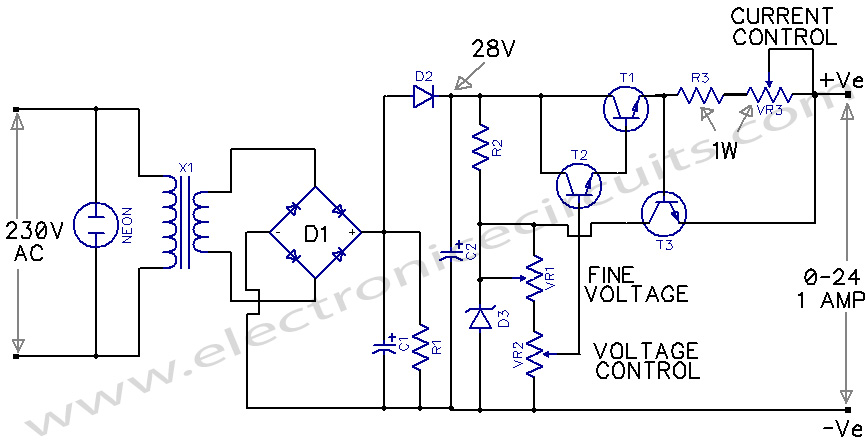
Variable Power Supply 0-24V circuit diagram

PARTS LIST
R11kΩ  0.5W
R2820Ω  0.5W
R30.6Ω  1W
VR1470Ω  LIN
VR210K LIN
VR310Ω 1W
C12200µF 50V
C2200µF 50V
D15A Diode Bridge
D22A Diode
D324V 500mw zener
T12N 3055
T2SL 100
T3BC 148B
X1SEC 24V, 1AMP

The pots used for voltage variation are 23mm carbon-film linear type and for current limit 10 ohm, 1w wirewound type is used. All the components can be connected on a group board. Necessary heatsinks should be provided for both SL100 and 2N3055.

Also you can try below 2n3055 power supply circuit using LM741 op amp IC.

REGULATED POWER SUPPLY USING 741 AND 2N3055

Please send your ideas, those are very important for our success…

Electronic Circuits Power SupplyRegulator Diagrams

Post navigation

Previous post
Next post

Comments (7)

  1. Jay says:
    July 31, 2010 at 10:58 am

    What is voltage regulation of 12V and 24V at full load current of 1 Amp?

    Reply
  2. Mahadev Pawase says:
    July 31, 2010 at 1:14 pm

    Thanx for the help. I have designed 0-24V power supply using your given ckt diagram & It is working smoothly.

    Thanx Thanx alot.

    Reply
  3. kushal says:
    November 6, 2012 at 12:42 am

    Can You Please mention how is the above circuit designed..? I mean the caluculations of resistence values and choosing particular transistors..?

    Reply
  4. Cherikhan says:
    February 5, 2013 at 8:21 pm

    This circuit is simple and usefull but not really stabilized its working without any error correction . thanks.

    Reply
  5. puneet says:
    June 17, 2015 at 12:09 pm

    dear sir

    what is the basic difference between smps and the above mentioned ckt

    Reply
    1. admin says:
      June 17, 2015 at 5:18 pm

      Smps is high efficient. So it save more energy. But this type (linear) power supply is simple,low risk for electrocution

      Reply
  6. Pingback: REGULATED POWER SUPPLY USING 741 AND 2N3055 - Electronic Circuits

Leave a Reply Cancel reply

Your email address will not be published. Required fields are marked *

  • Diagrams
  • Privacy Policy
  • Software
  • Contact

Recent Posts

  • LM317 CONSTANT CURRENT CALCULATOR
  • 5V buck converter – LM2576 simple DIY project
  • ICL7107 PANEL METER
  • Precision 1Hz clock generator circuit
  • Toggle to Momentary Switch Using 555 Monostable

Categories

  • Circuit Tutorials
  • Electronic Circuits
  • Electronic Software

AC Projects Alarm Circuits Amplifier Circuits Amplifiers Antenna Circuits Battery Charger Calculator software Circuit Designer Control Circuits Converter circuits Crossover Circuits Data Sheets Digital Circuits Electronic Switch Flasher Circuits Game Circuits IC Programmer IC Programming Indicator Circuits LED Circuits Light Circuits Logic Circuits Measuring Circuits Meter Circuits Microchip Motor Circuits Music Circuits Oscillator Circuits PCB Designer PIC Power Amplifier Power Guard Power Supply PreAmplifier Circuits Radio Circuits Regulator Circuits Regulator Diagrams Regulator Schematics RF Schematics Sensor Circuits Tester Circuits Timer Circuits Transmitter Circuits Tutorials Vacuum Tube

©2025 Electronic Circuits | WordPress Theme by SuperbThemes